4 Knuckles: Modular Circuits for Machine Control
4.1 Chapter Introduction
Many machine controllers (and most that are open source) are controlled with monolithic control boards, where the control logic is centralized and boards include a limited set of IO devices (motor drives, inputs etc). It is common to repurpose monolithic boards to control machines that they were not originally intended for, but this practice can quickly hit limits (2.1.2). I won’t belabour the point, modular systems have advantages that are probably familiar to readers of this thesis.
There is a growing trend in open hardware towards modular circuit ecosystems, but they hadn’t emerged when I was starting this work. Also, most industrial automation systems are already modular, but are not hackable. Without a herculean reverse engineering effort, I would not have been able to use them to develop the other methods in this thesis, many of which require that I make edits to fairly low levels in the controllers. So, following in a long Center for Bits and Atoms tradition, I developed my own set of modular circuit hardware.
This system of circuits was a key enabler of the methods and systems that I developed in this thesis, but there is nothing completely new or unique about the hardware itself; my contributions are in the networks (2), programming models (3) and controllers (5, 6 and 7). It is best to consider this chapter as a methods section, with some discussion on the design and use of modular circuits as a practice - and how that practice connects to the architectural topics raised in other chapters. In another lens this is a motivating chapter, showing how we might be able to flexibly re-use modular hardware if we are successful in our attempts to re-configure control architectures.
So, below I include a brief discussion of the challenges for modular circuit systems 4.1.1 and then the set of circuits that I used to develop the content of this thesis. I call these Knuckles because they aspire to help us spread computing and control into the joints and nodes of our networks. Section 4.2 enumerates the control modules, 4.3 explains a swappable network hardware layer that I develop (which allows us to re-use modules across different network link layers, basically a meta-connector) and in Section 4.4, the nodes that I developed as dedicated message passing devices. In the discussion section, I highlight some of the ways that I have used these boards, showing device re-use in Section 4.5.1, and machine retrofitting in Section 4.5.2. I close the chapter by discussing the importance of ecosystem hackability (4.5.3) and some thoughts (4.5.5) on the relationship between power networks (which should be Directed Acyclic Graphs (DAGs)) and data networks (which, ideally, can be Cyclic Graphs).
4.1.1 Challenges in Modular Hardware Design
One of the primary challenges that sets modular hardware apart from modular software is that hardware is more difficult to make generalizeable; not only do specific tasks require specific hardware arrangements, components also need to interface across variable networks and at variable power levels. For example even though motor drivers are all essentially the same, there is a broad range of particular motors to drive, each needing i.e. more or less current, voltage, and variable packaging. Besides trying to generalize circuit modules for different tasks, we may want to deploy them in different contexts: motor controllers can be found in battery powered robots or drones, or in mains-supplied machine systems (each running on different voltages). There is also a heterogeneity of networking solutions available in mechatronic systems (which I discussed in 2.1.1): users of hardware modules may want to integrate a new device on a CAN Bus, over Ethernet, or simply via USB or UART, etc. All of this means that even for the same core function, we need to develop many possible pieces of hardware to appropriately suit the task and context. In software (where modules are more common), computer languages, package managers, operating systems and compilers make it easier to deploy the same lines of code in many different contexts - we hardly even think about it when we can write code on our PC’s and then have it run identically in a datacenter, or on a different instruction set, etc.
Another challenge for modular hardware design is to develop a set of modules that can be broadly applied across different tasks. From an economic perspective, it is more productive to develop a smaller set of modules and apply them to many tasks to better amortize module engineering costs. From a systems engineering perspective, it is better to make general purpose modules that can be applied across many tasks because this means systems assemblers can pick from a smaller catalog of parts to accomplish their goals. Of course this is most of why we want to build modules in the first place: by breaking a system into parts, we can easily re-assign those parts in new systems. The challenge is in making performant and simple modules that can also be “assignable” to many different tasks. Much of that challenge applies more to the programming models within our devices, but the hardware matters as well.
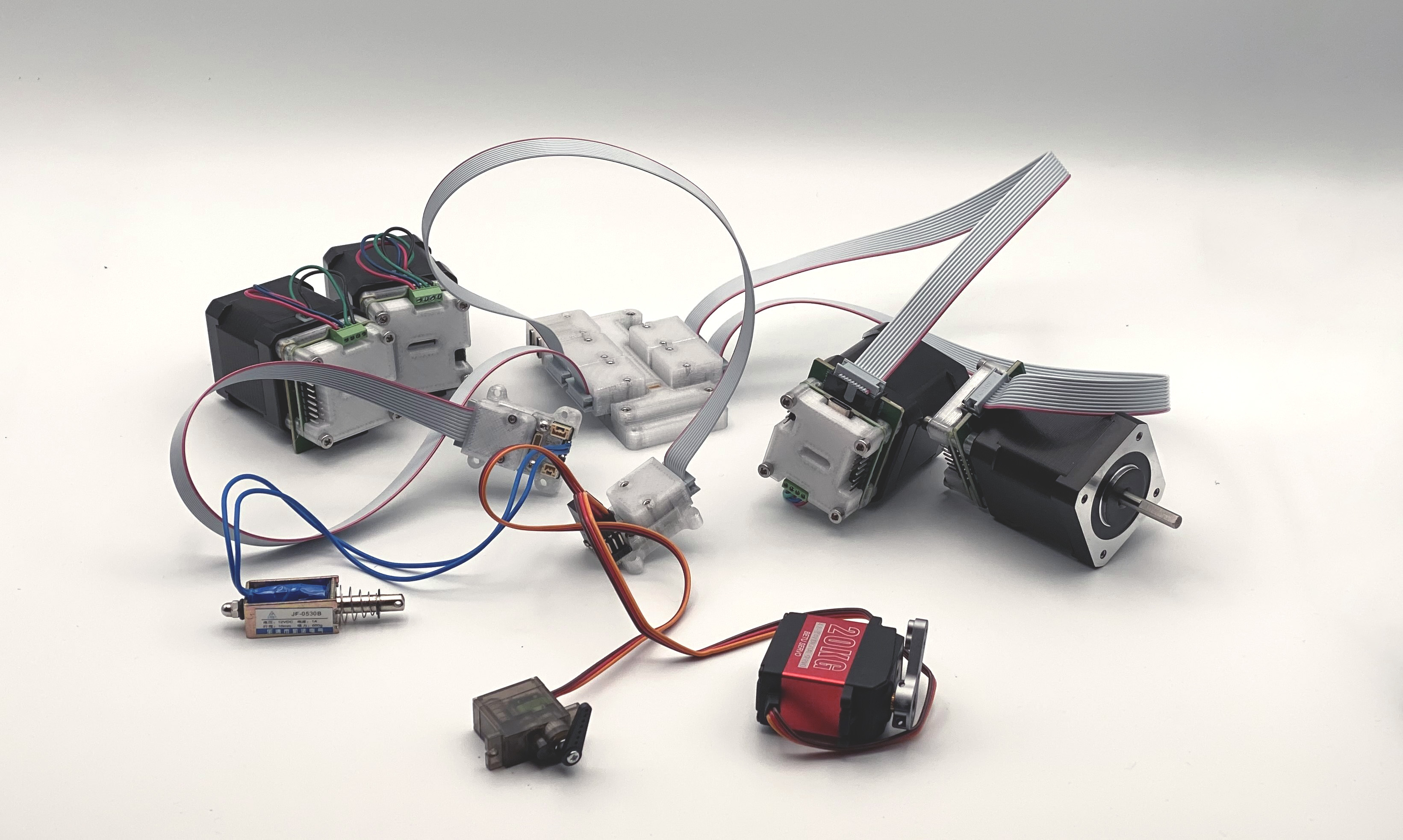
4.2 Knuckles Devices
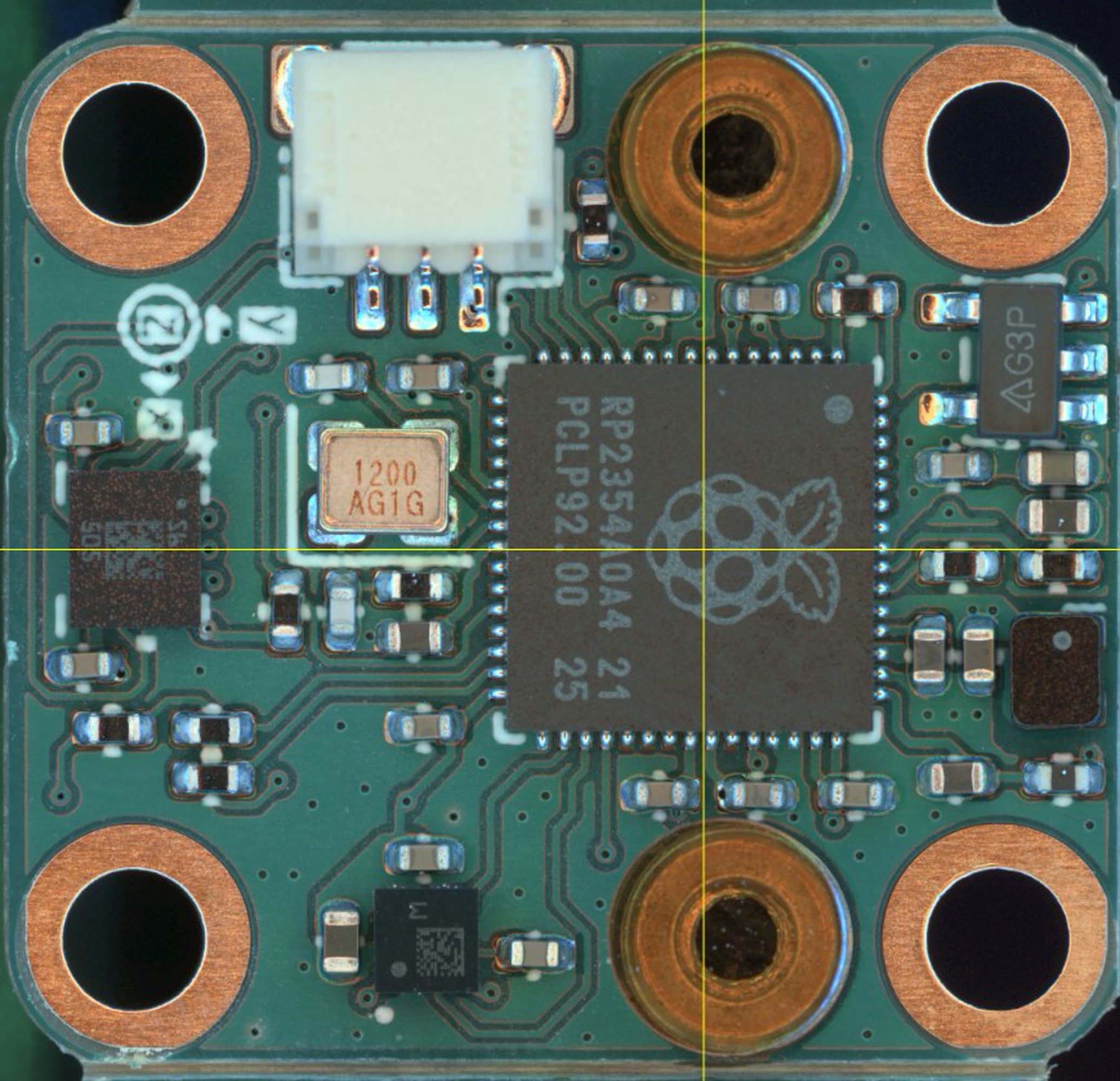
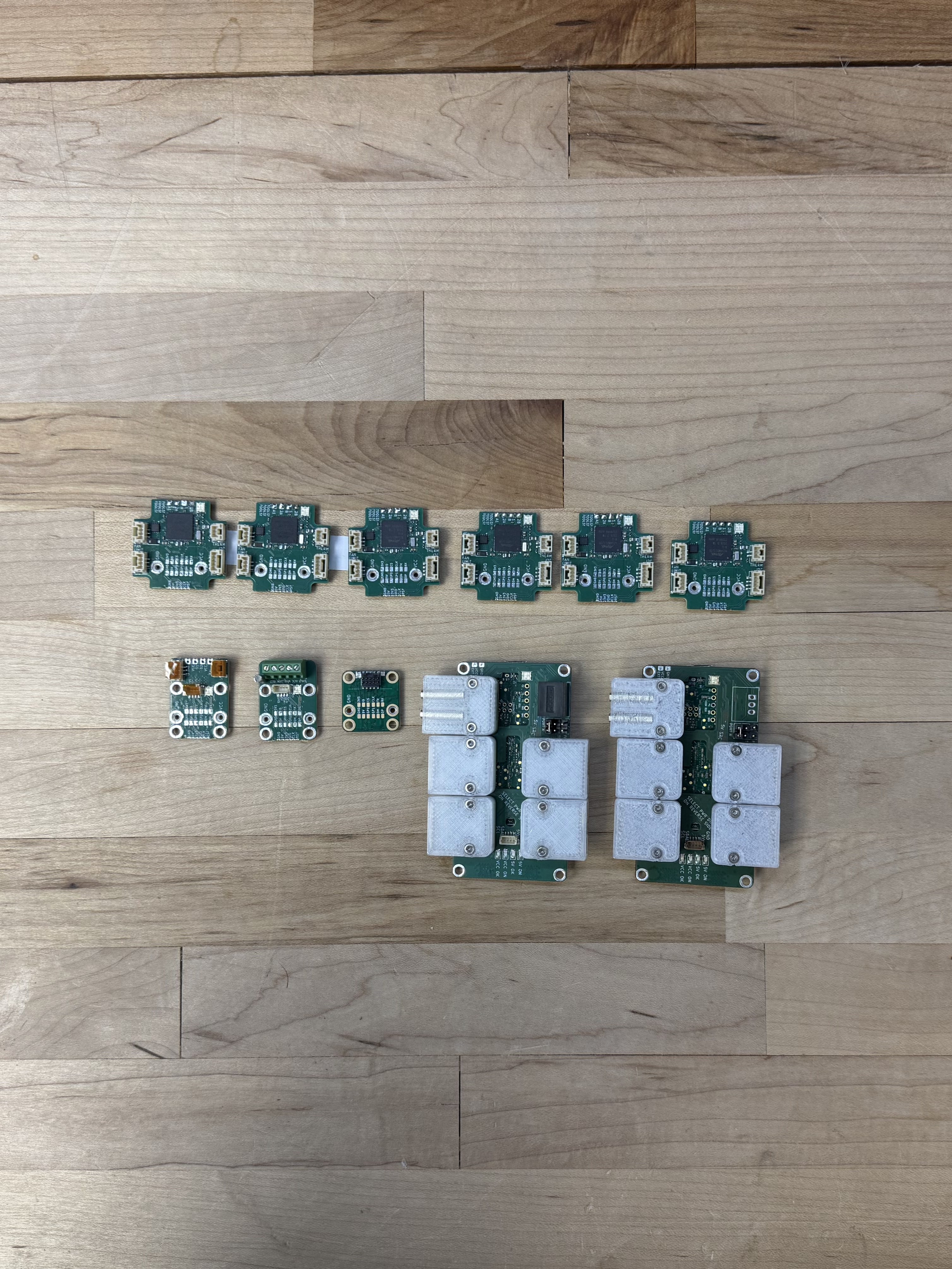
The current kit of circuits includes five devices, which are all below. This set - and some ad-hoc inclusions (4.5.3) cover the tasks in this thesis. I use a mixture of microcontrollers; SAMD21’s for simple boards, SAMD51’s for the stepper driver, and more recently the RP2350. The availability of cheap, high-powered microcontrollers is a big part of what makes this project possible.
The closed-loop stepper driver appears the most frequently, I write about it at length in Section 5.4.
The hbridge driver is useful in many contexts as a generic DC load driver. I discuss those in Section 4.5.1.
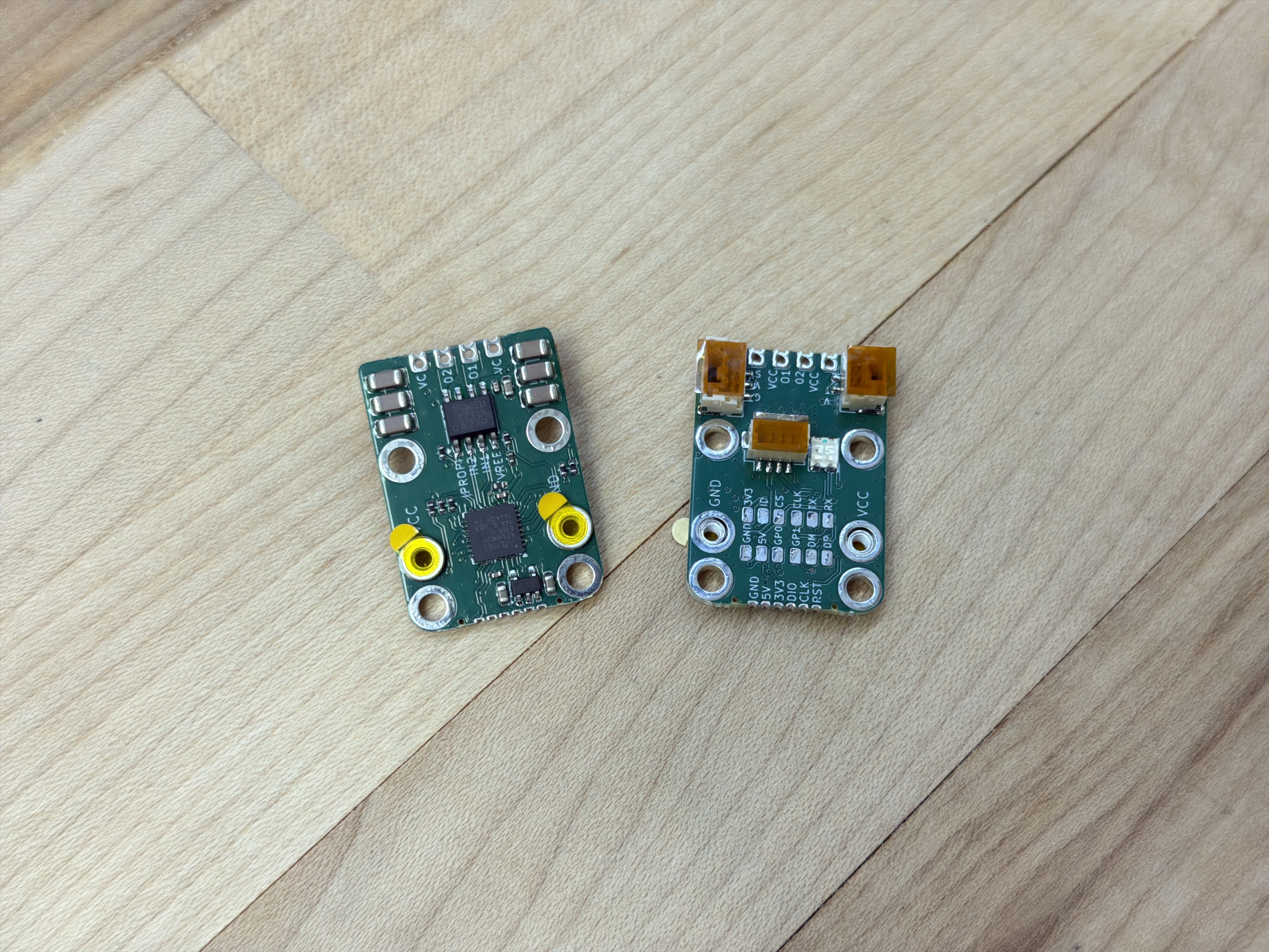
The loadcell amplifier can sample at nearly 4kHz. I use it to measure pressure for modelling polymer flows in Chapter 6.
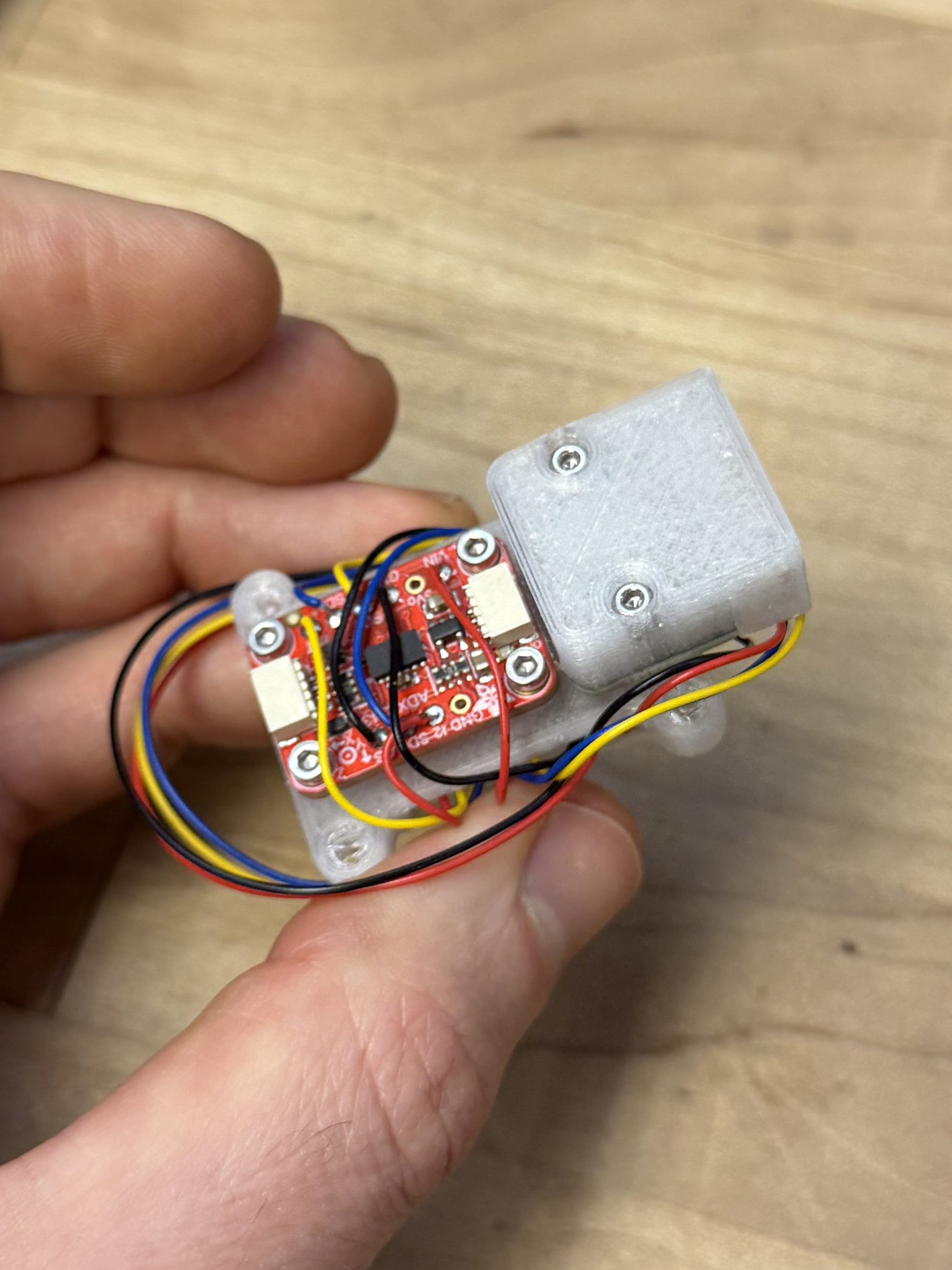
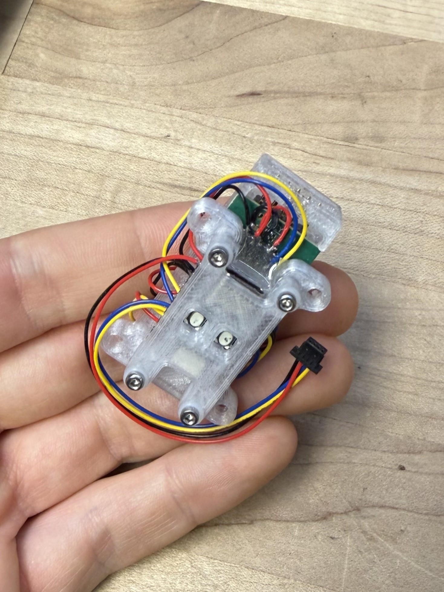
![]()
I developed the accelerometer module recently, but have not completed writing its firmware. I discuss its future utility in Section 5.8.4.
The deadbugger (named after the ad-hoc electronics assembly practice of building deadbug circuits (1981), (2018)) is an odd module; I developed it to cover edge cases in modular systems where we simply want to turn something on or off, and to drive 5V loads like hobby servos. It is essentially just a SAMD21 microcontroller, with our network interface (below), exposed connectors / pads, and a large 5V regulator. I discuss it as well in Section 4.5.1.
4.3 Knuckles Backpacks
One of my ongoing frustrations with circuit development was that the board designs were often coupled to systems design. I would build a new networking layer, design a series of circuits for that layer (including the correct connector and interface hardware), and then I would subsequently improve or modify the networking layer, rendering that set of circuits defunct. This was seriously unproductive, but is representative of something that is true more broadly in networked hardware: link layers are heterogeneous.
That is to say, in different systems contexts, we want to use different types of networking. In a high performance machine controller, we probably reach for EtherCAT, ProfiNET (etc) - but these are expensive and complex to integrate. For small systems with just a few devices, a simple USB connection to each module is sufficient and productive, since everyone has USB hardware already “lying around” (2023). In the middle ground we can use simple wired links like CAN or ad-hoc UART based busses, and for remote systems we want to implement wireless links like BLE, WiFi or (for long ranges) protocols like LoRa. Ideally, we would be able mix and match these systems - using some wireless devices, some wired, etc.
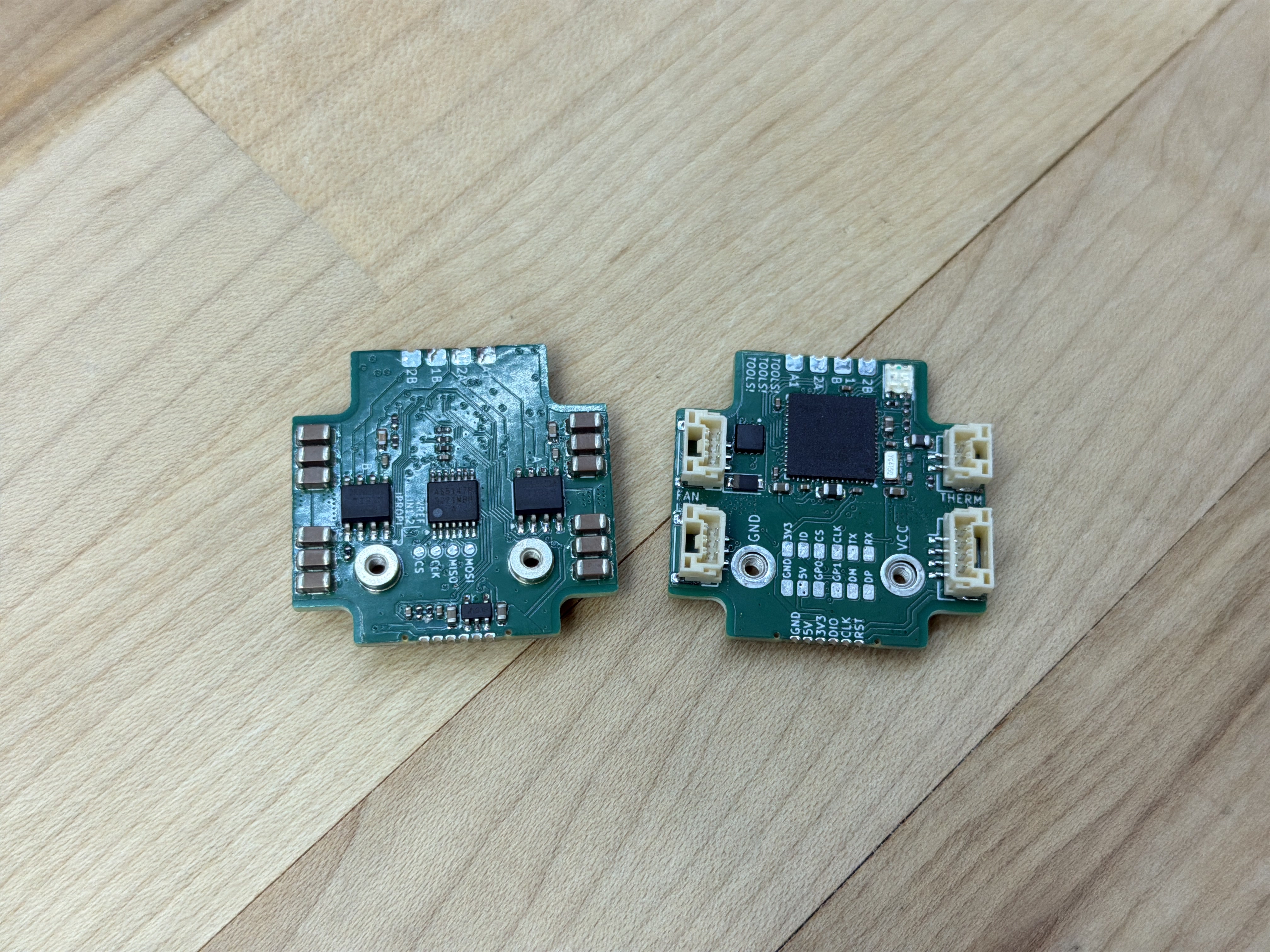
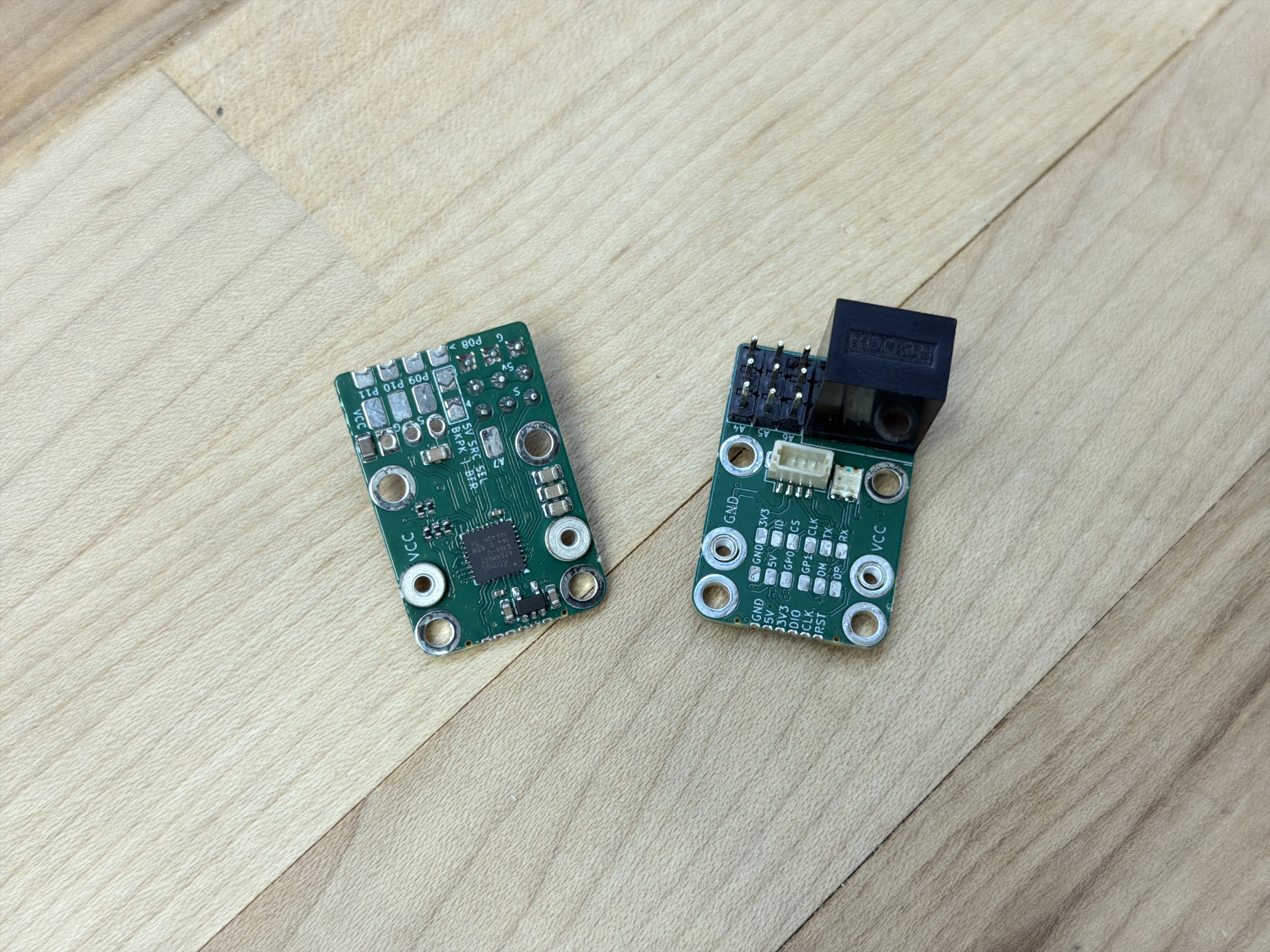
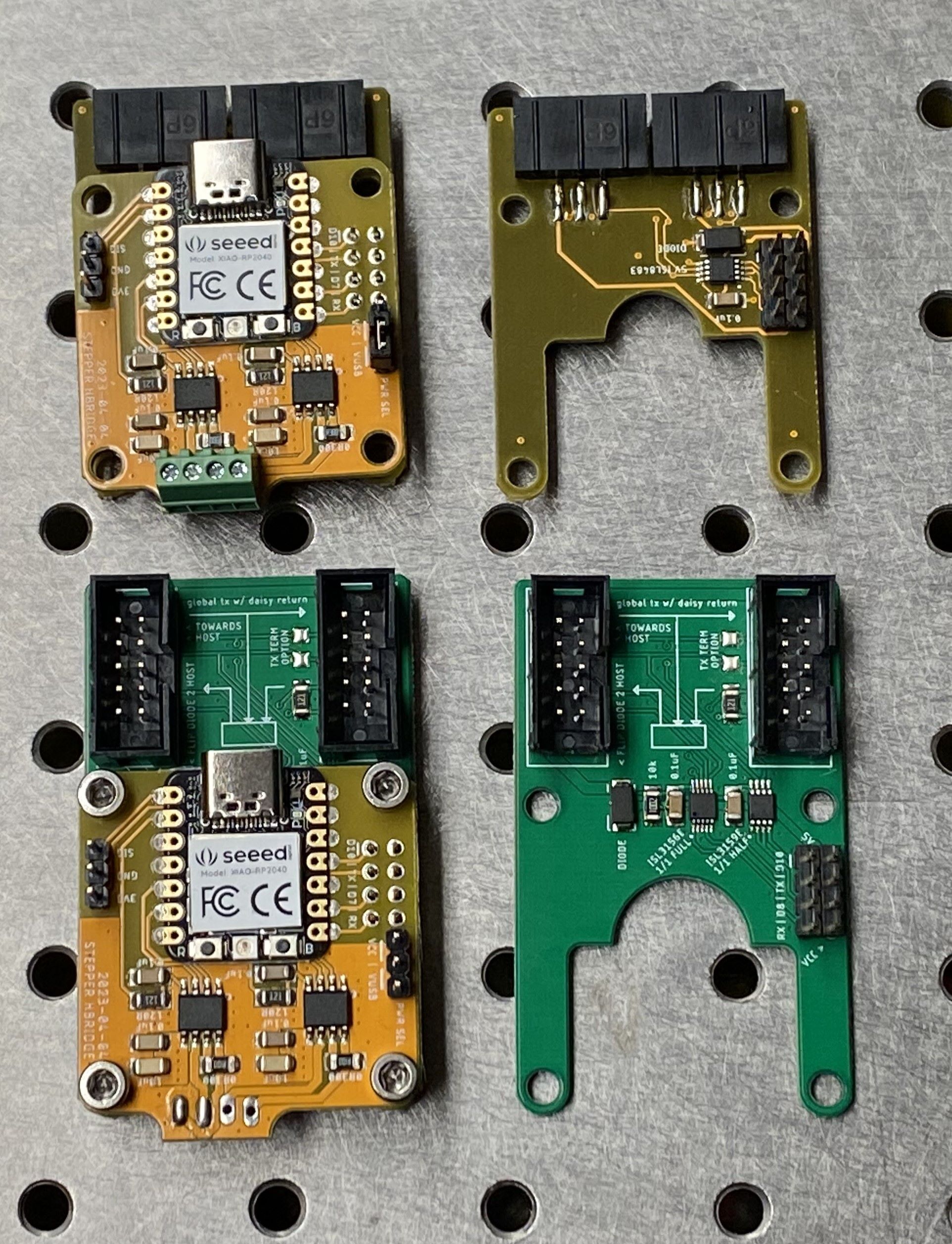
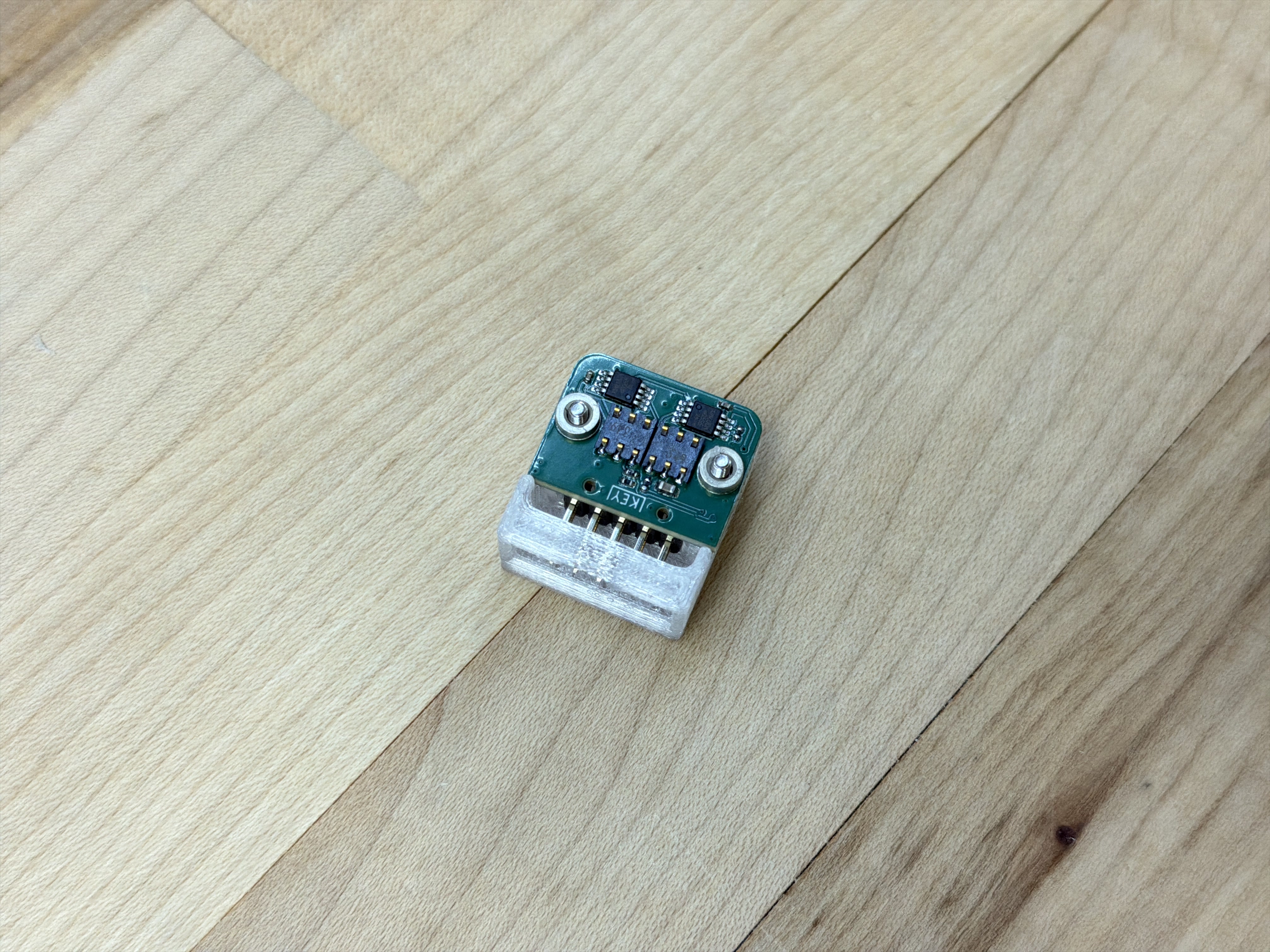
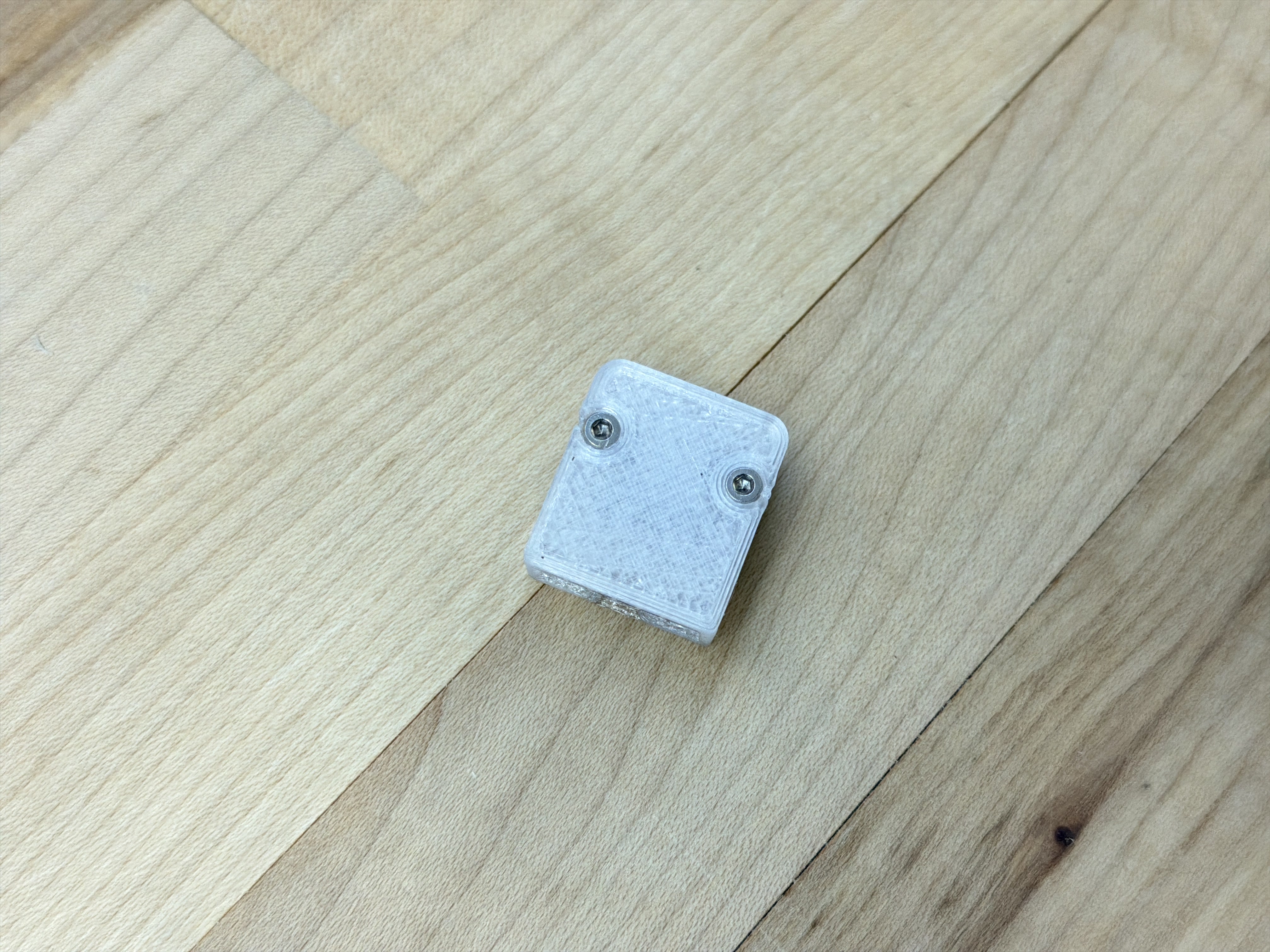
To counter this issue, I began developing what I call backpacks. These are PHY level modules, i.e. they interface from our devices’ microcontroller to various links. Early backpacks used a simple eight pin header to interface between devices and link layers, some of which I show in Figure 4.7. This enabled me to simultaneously develop link layers and modules, without coupling the electrical hardware.
Using backpacks means that I can build \(a:\) a set of modular circuits and \(b:\) a set of modular PHYs, and rapidly combine them depending on the context rather than filling out the \(a \otimes b\) matrix of unique circuit designs.
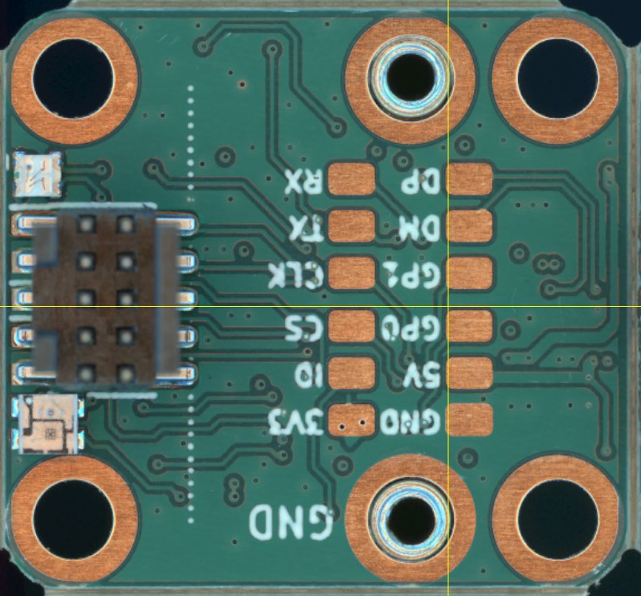
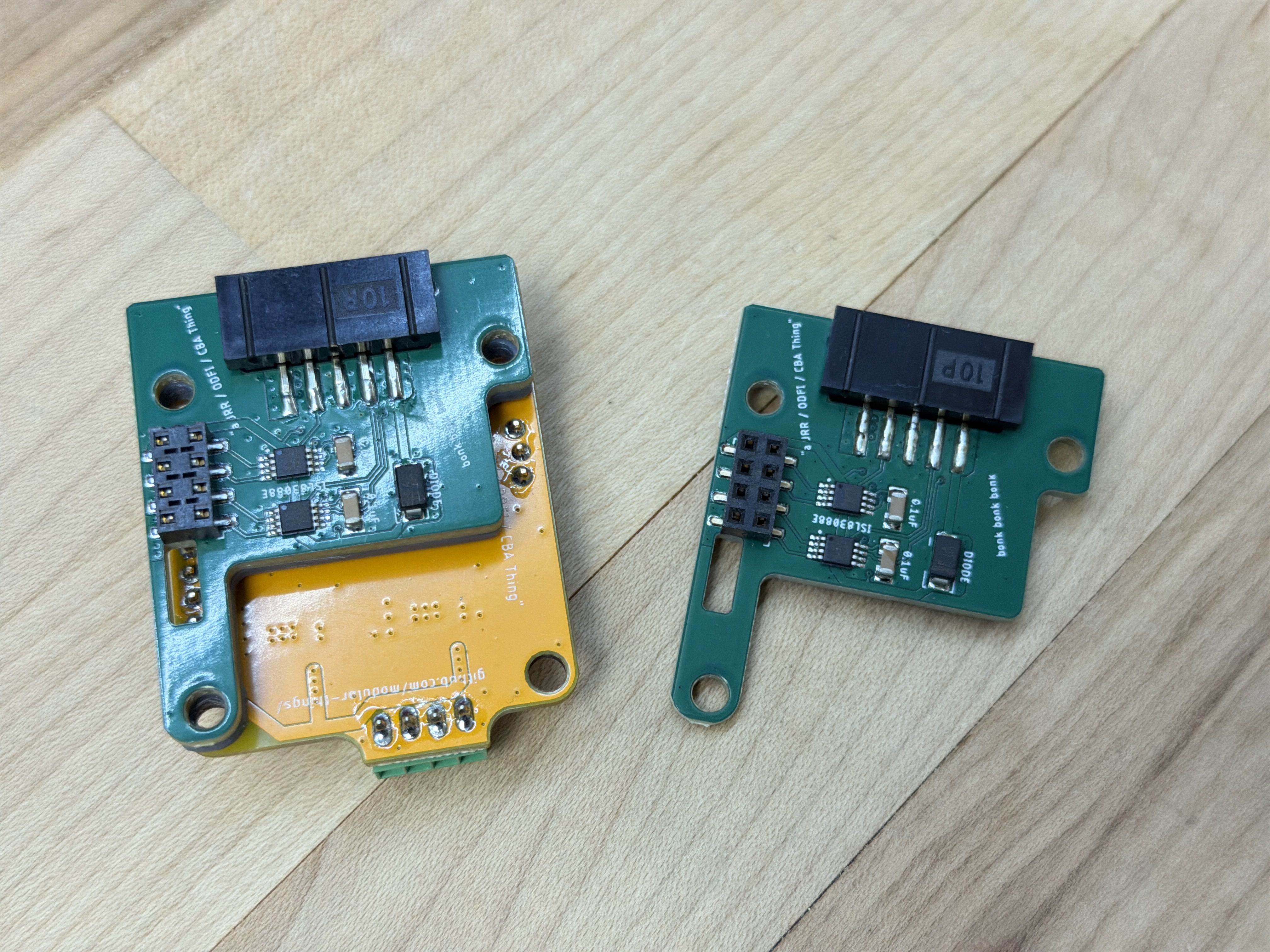
Backpacks use two 2x3 spring-loaded connectors (which are made cheap and ubiquitous by their intended use case as SIM card connectors) to connect to exposed pads on the host module. They mount to that module using surface-mount standoffs: through-hole standoffs on the backpack, and threaded (M2 size) on the module. The stand-offs do double duty as power connectors, they are rated to carry up to 70 Amps of current. The Backpack interface is \(20 \times 17.5mm\), with standoffs \(15mm\) apart on center. It specifies a pinout, which is below in -#tbl-knuckles-backpack-pinout.
| Pin | Name | MCU Pin / Peripherals | Note |
|---|---|---|---|
| Standoffs | — | — | — |
| GND | Power Ground | n/a | |
| VCC | Power Voltage | n/a | |
| Left Col | — | — | — |
| GND | Data Ground | n/a | |
| 5v | 5 Volts In* | n/a | Sourced from Network |
| GP0 | GPIO 0 | Any / GPIO | |
| GP1 | GPIO 1 | Any / GPIO | |
| DM | Data Minus | USB_DM, LVDS_LO | |
| DP | Data Plus | USB_DP, LVDS_HI | |
| Right Col | — | — | — |
| 3v3 | 3.3 Volts Out* | n/a | Sourced from Module |
| ID | ID / Type | ADC | Backpack Identifier |
| CS | Chip Select | SPI_CS | |
| CLK | Data Clock | SPI_SCLK, UART_CLK, I2C_SCL | |
| TX | Transmit* | SPI_COPI, UART_TX, I2C_SDA | |
| RX | Receive* | SPI_CIPO, UART_RX |
I have not formalized this into a complete spec, which would need to include more detail. A few notes on the design of the pinout:
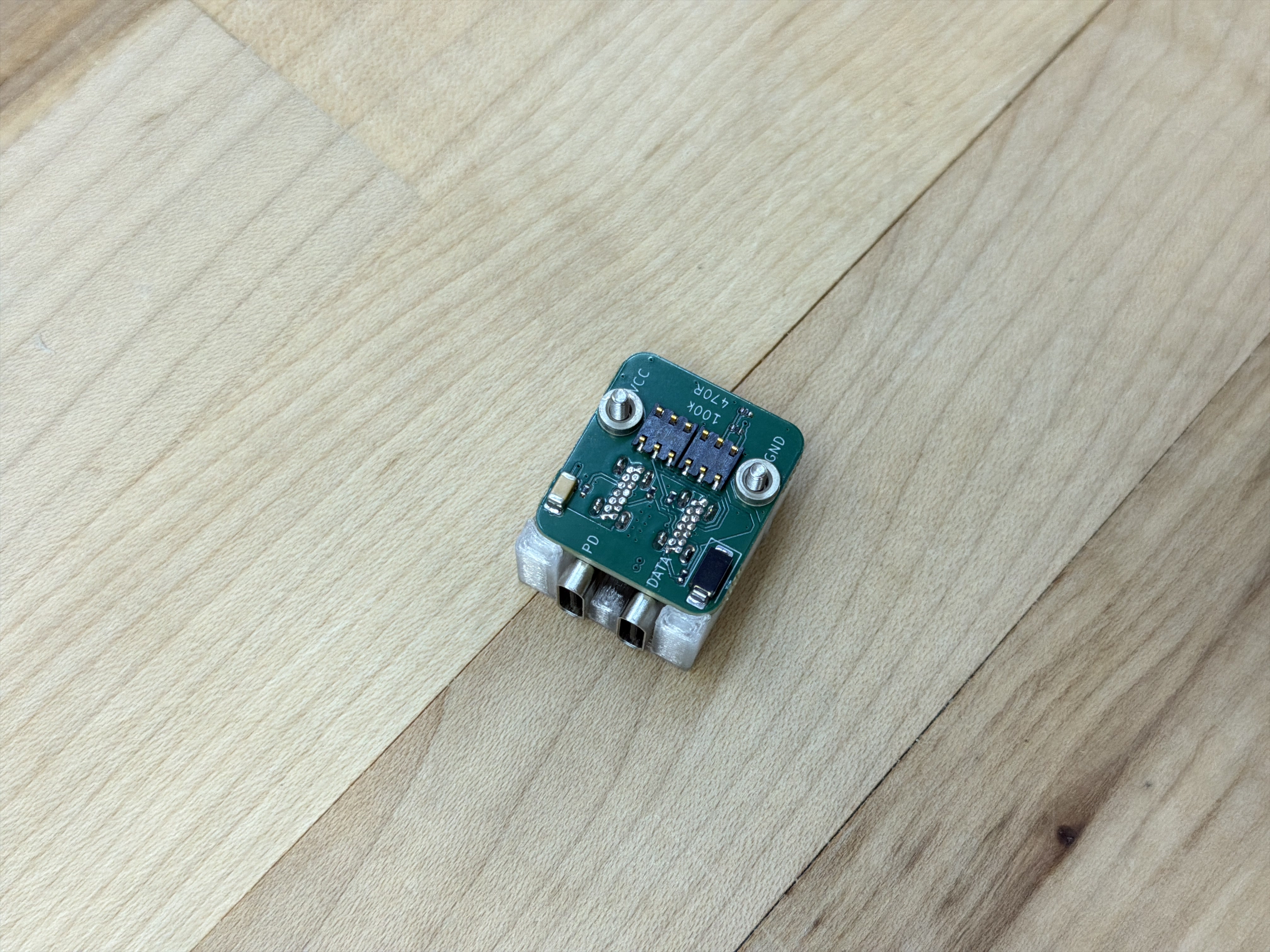
- The ID pin is connected to a voltage divider on the Backpack: by specifying resistance levels in that divider (the top of which is connected to 3v3), microcontrollers can read the voltage to ascertain which type of backpack is connected. This is an ad-hoc solution to the problem presented by the intended use, where modules can load variable drivers on boot to run backpacks that may have been swapped since the last firmware update.
- I specify that the 5v pin delivers “logic” power to the module, and the 3v3 pin returns regulated power to the backpack. In retrospect, this was an odd choice when compared to other modular systems where it is typical that modules include their own voltage regulators, stepping down from their “main” power input, i.e. high voltages in the case of motor drivers. This arrangement assumes a tighter integration between network power supplies and modules. However, it makes it very easy to outfit simple sensors (that only require logic-level power), and to power devices’ microcontrollers to configure them before delivering potentially dangerous levels of power.
- Many pins do double duty, i.e. CLK, TX and RX are available for either UART, SPI or I2C integrations. I presumed that use of these peripherals would be mutually exclusive on any given backpack. Modules are free to implement as many of these as they like, and replace empty sets with general purpose GPIO or connect all peripherals to anticipate variable backpacks. However, the pinout should be modified to clearly reflect which are available on the module.
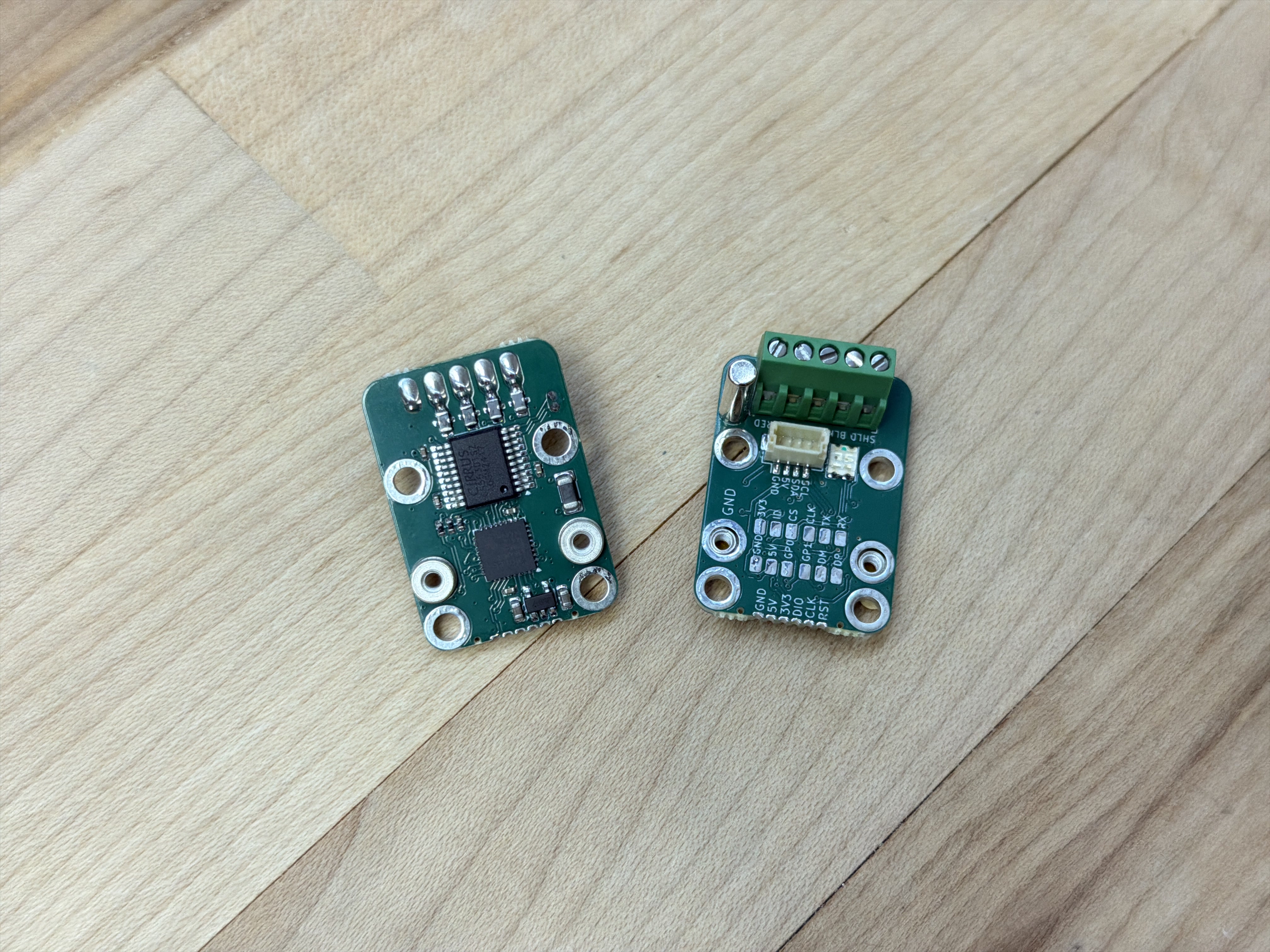
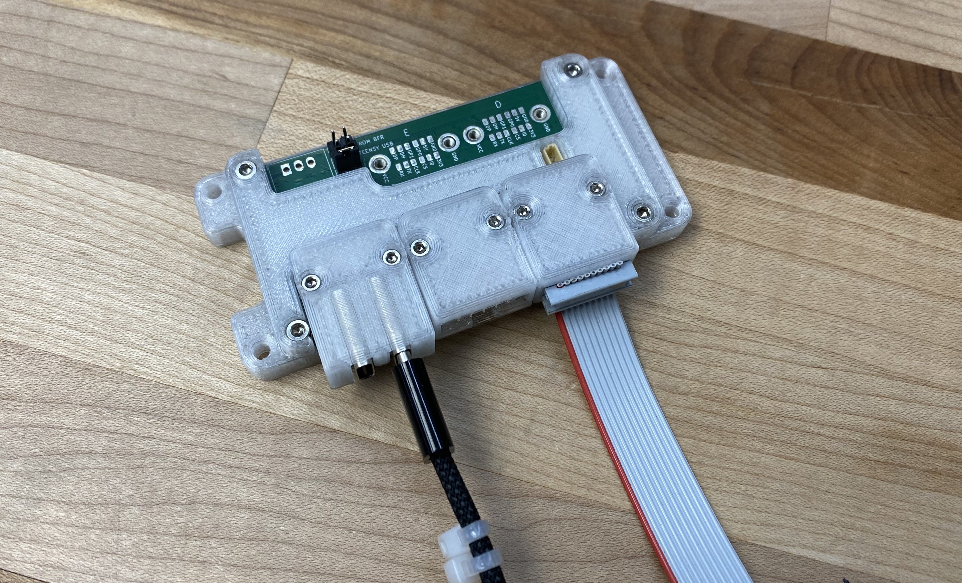
The UART/RS485 Backpack (above, 4.10) connects the module’s UART peripheral to others over RS485 (a voltage signalling standard), using a 10-pin IDC connector and cable. This technology is extremely simple and common, but (with well written firmware) can be very high performance.
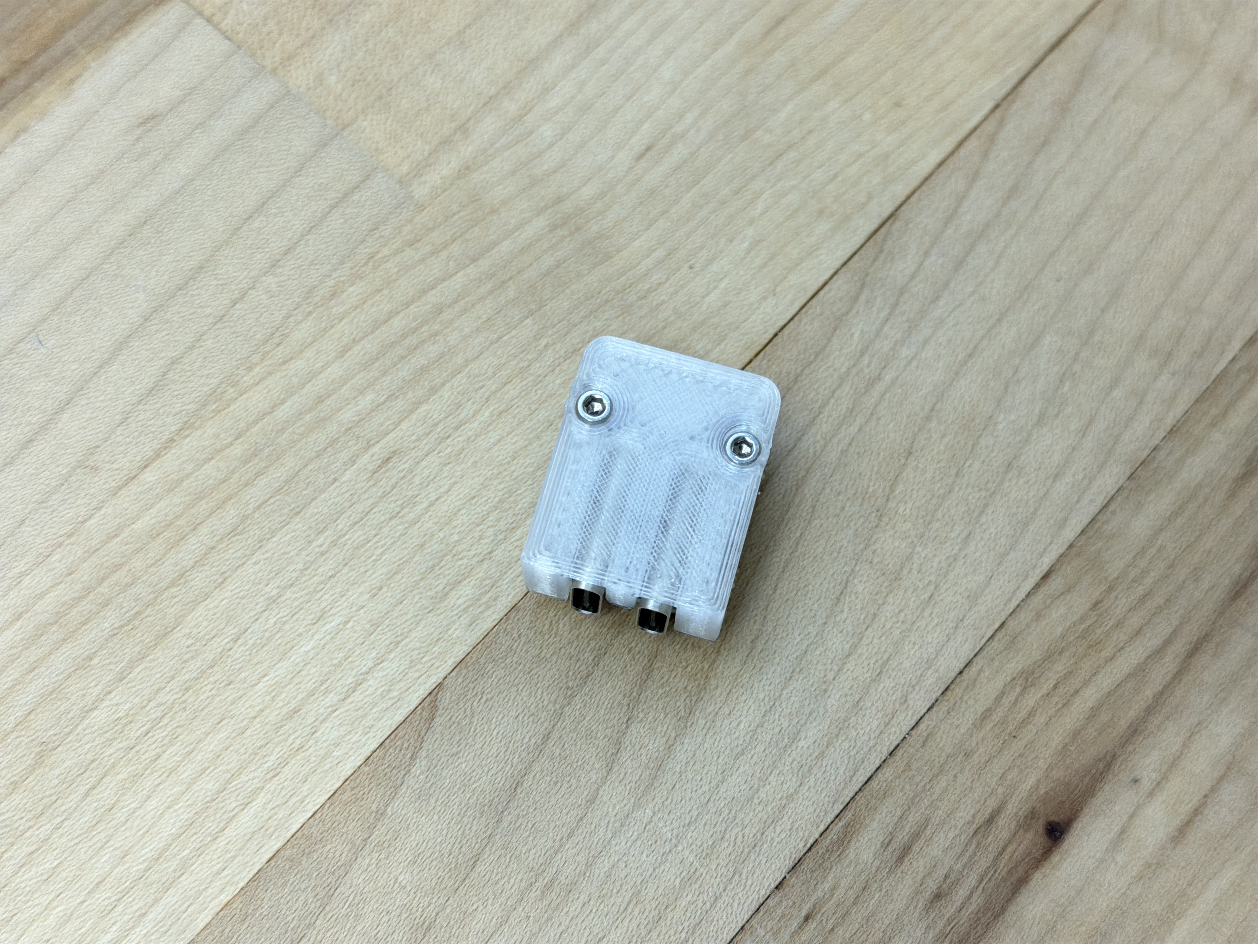
The USB Dually Backpack (above, 4.11) connects one USB-C connector to the module’s mcu, and the other to a USB Power Delivery Decoy chip, which handles the protocol required to request high voltage power from modern USB-C chargers and power banks. This lets us connect to and power machine systems or modules using ubiquitous power supplies.
In many cases, the host microcontroller contains the hardware required to interface directly into the physical layer - i.e. the link layer logic is implemented in the host microcontroller. For example just about every microcontroller on the market includes one UART peripheral, and probably one SPI, and often a USB block. In these cases the backpack interface lives between OSI layer 2 (Data Link) and 1 (Physical, aka PHY). For example the backpack at the left of Figure 4.9 promotes UART TTL (Transistor-transistor Logic, which comes directly out of the microcontroller) to RS485 - a larger, differential voltage level that improves noise immunity. The microcontroller can easily implement the protocol that promotes that UART peripheral (which simply sends and receives bytes) into a proper Link Layer (encapsulating packets and catching errors). For some more discussion on how these layers are organized, see Section 2.2.3.
It is common for more complex link layers like EtherCAT and BLE to be integrated via standalone link layer controllers. This is because link layer operation is a time critical task, and microcontrollers that are running application code are not guaranteed to be available to handle packet frames in time. In these cases, it is common for the link layer controller to be interfaced to the host microcontroller using another protocol that is effectively hidden in the OSI layers model. For example EtherCAT and Ethernet controllers are normally connected via SPI, USB controllers via UART, etc. These can be accomodated in the backpack ecosystem, integrating the link controller on the backpack and mounting those SPI / UART connections via the backpack pinout.
I want to note that this sneaky insertion of (what is effectively) an additional network link in the OSI model is a common design pattern in embedded device development. There is even a set of standardized link-controller-to-phy interface for Ethernet: the MII/RMII (2022) (1998) (Media Independent Interface, or the Reduced version) enables ethernet to be broadcast across various media: these are, again, effectively GPIO specificiations. In optical networking, we find things like Small Form-factor Pluggable “network interface modules” (SFPs) (2001) that allow individual ports to be reconfigured to use different types of trancievers. These are often even hot-pluggable.
Obviously the sticking point is that we would all have to agree on the backpack layout. While this may seem unlikely, I would contend that it is a design pattern worth looking at. GPIO based interfaces have already been productive in open hardware, and even have two apparent hardware-design rivals (Adafruit and Sparkfun) sharing one design pattern in Qwiic / Stemma (they are the same thing). The shared value in such design patterns is the tricky engineering on either side of the interface doesn’t have to be duplicated relentlessly.
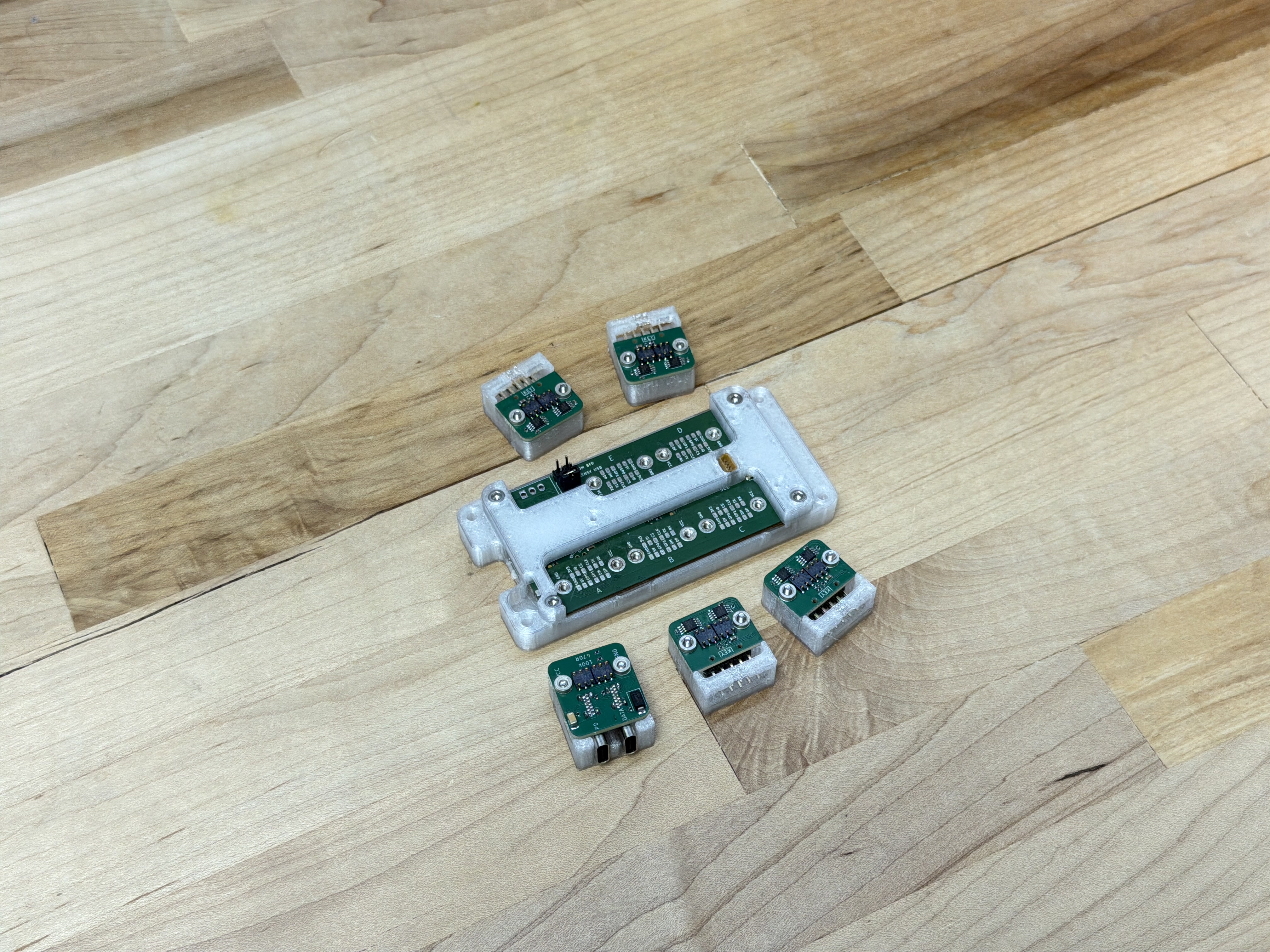
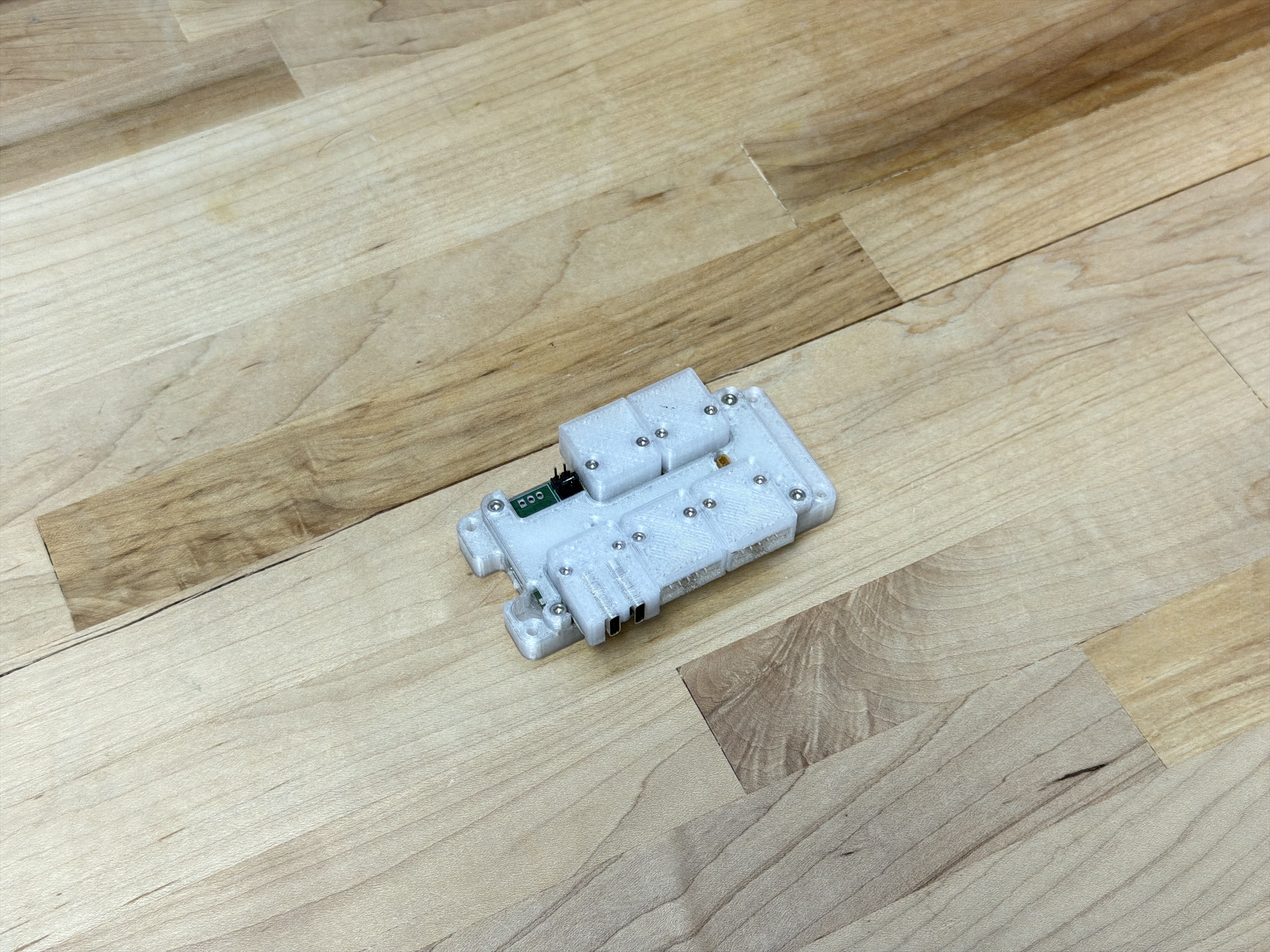
4.4 Knuckles Hubs
OSAP and Pipes are agnostic about device network architectures, i.e. there is no distinction made between “routing” devices and “endpoints.” This means that any knuckles device can implement multiple backpack connectors, enabling it to connect to more than one device and serve dual duty as a device and a kind of network router. In practice, networks are faster overall when their graphs are short, i.e. where we have very fast routing devices with very many ports, keeping the total number of hops between devices low. For this, I developed on hub device (pictured below), that uses a high performance mcu and has five Backpack interfaces. In addition to use in message passing, we can implement some firmware here for system control and management.
The hub also provides some power management functions: we can shut off downstream ports’ logic (5v) and device power (0-48v). This provides a convenience for configuring systems-level safety: the hub can turn system components off when i.e. watchdog conditions are not met in the case of watchdog hangups or other failures. It is also valuable to be able to remotely reset devices by simply power cycling them.
4.5 Discussion
4.5.1 Device Re-Use
In the introduction to this chapter I discussed how we would like to have hardware modules that are generalizeable across tasks. While this is primarily a challenge in the development of module firmware and control, the hardware also needs to be designed with enough affordances that it can be reconfigured.
HBridge connect electrical loads to voltage and ground through either a forwards or backwards path using four switches arranged in an “H” looking configuration, hence the name. They are most often used to drive DC motors, but of course any generic electrical load is valid: heaters, solenoids, etc. We can also use each leg independently to drive separate uni-directional loads (each being used as a “low side switch”).
On the HBridge knuckle, I included a connector for the HBridge’s outputs, and also an input for a thermistor (to read motor or other temperatures), and a generic three-pin connector, hooked up to an ADC - we often simply want one other pin to connect to the world.
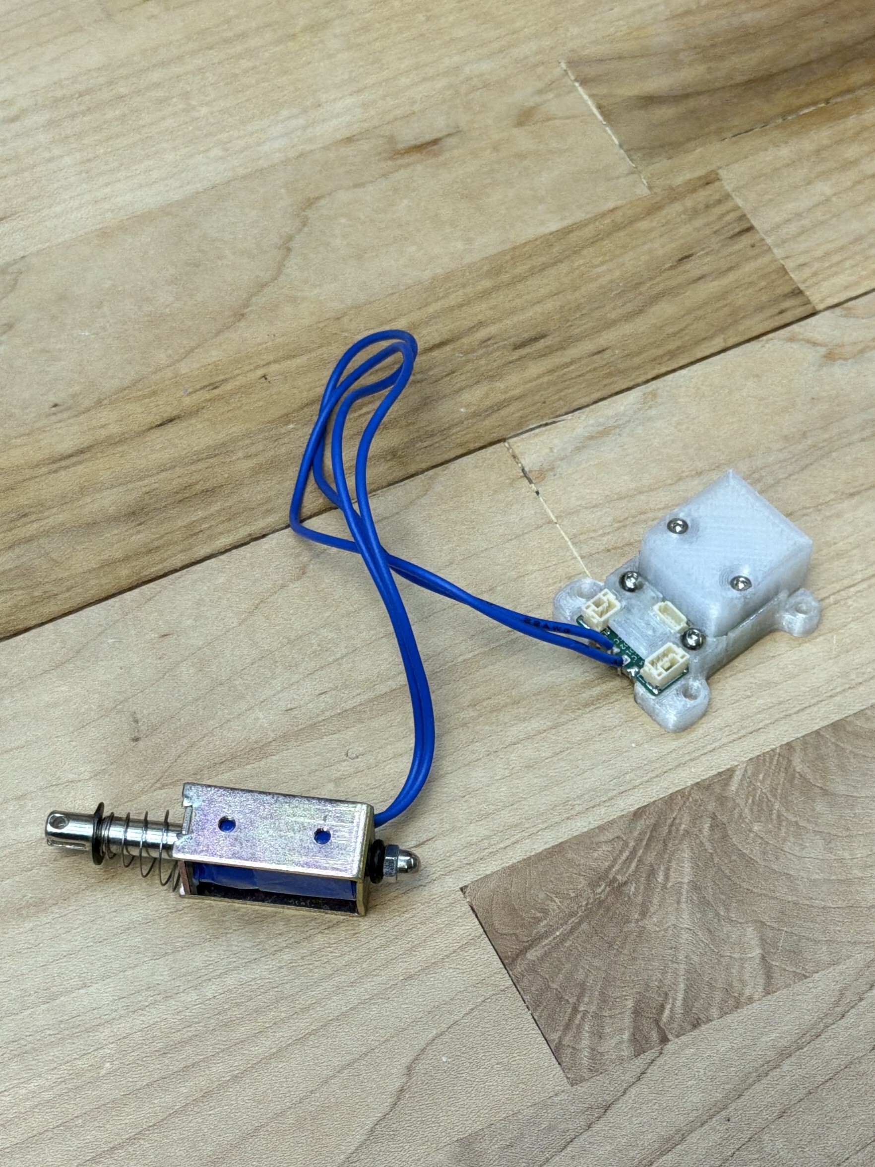
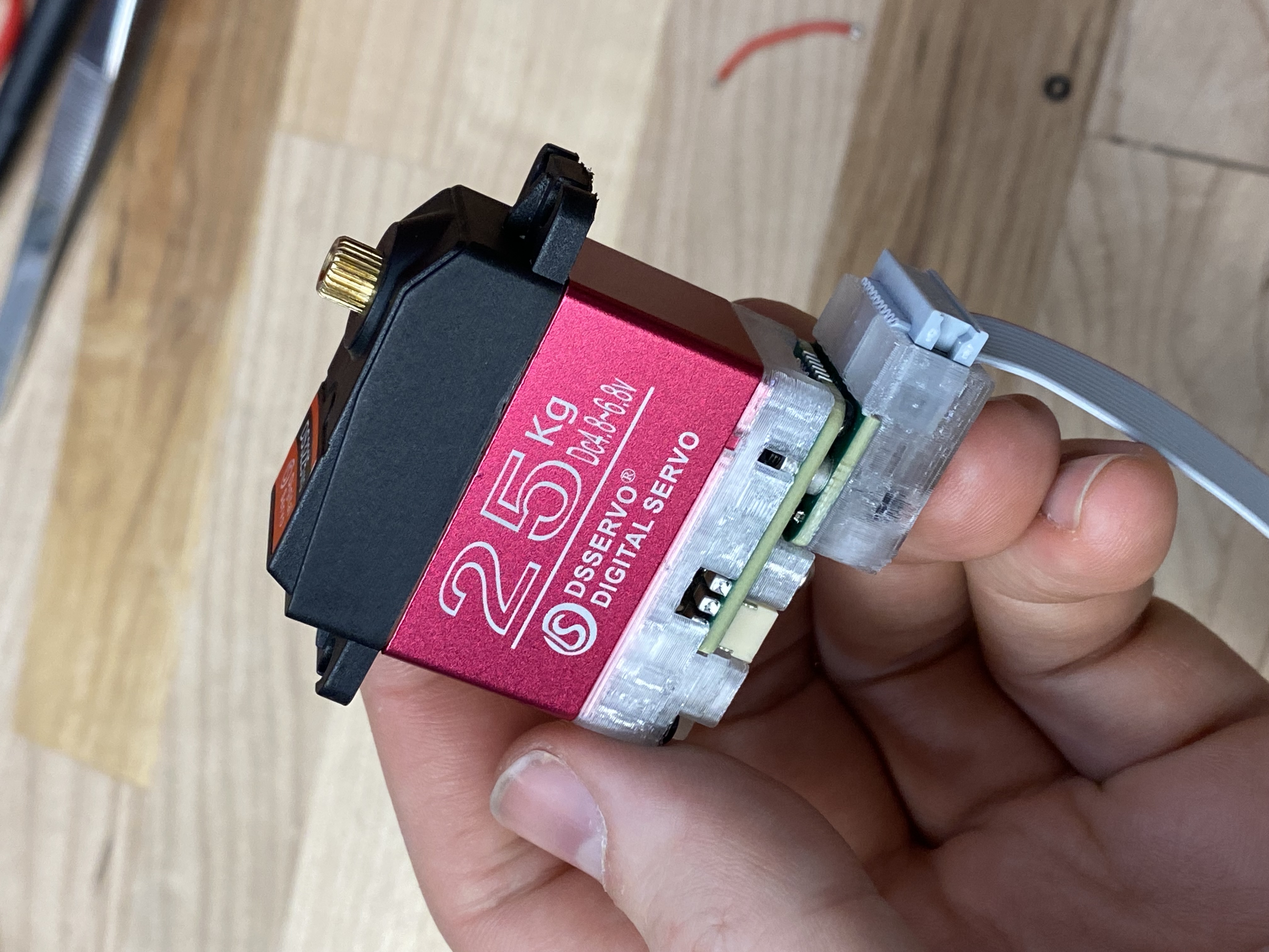
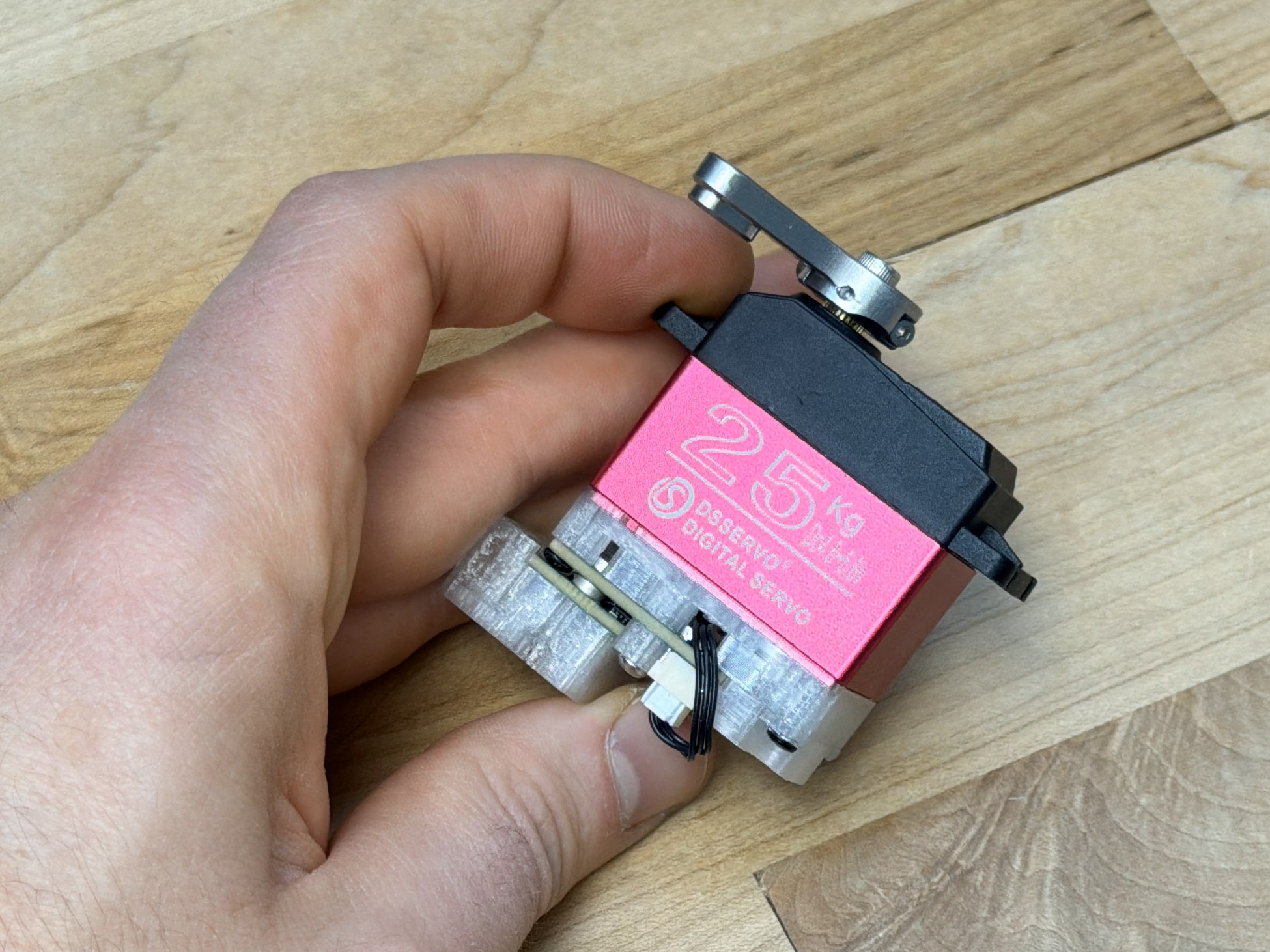
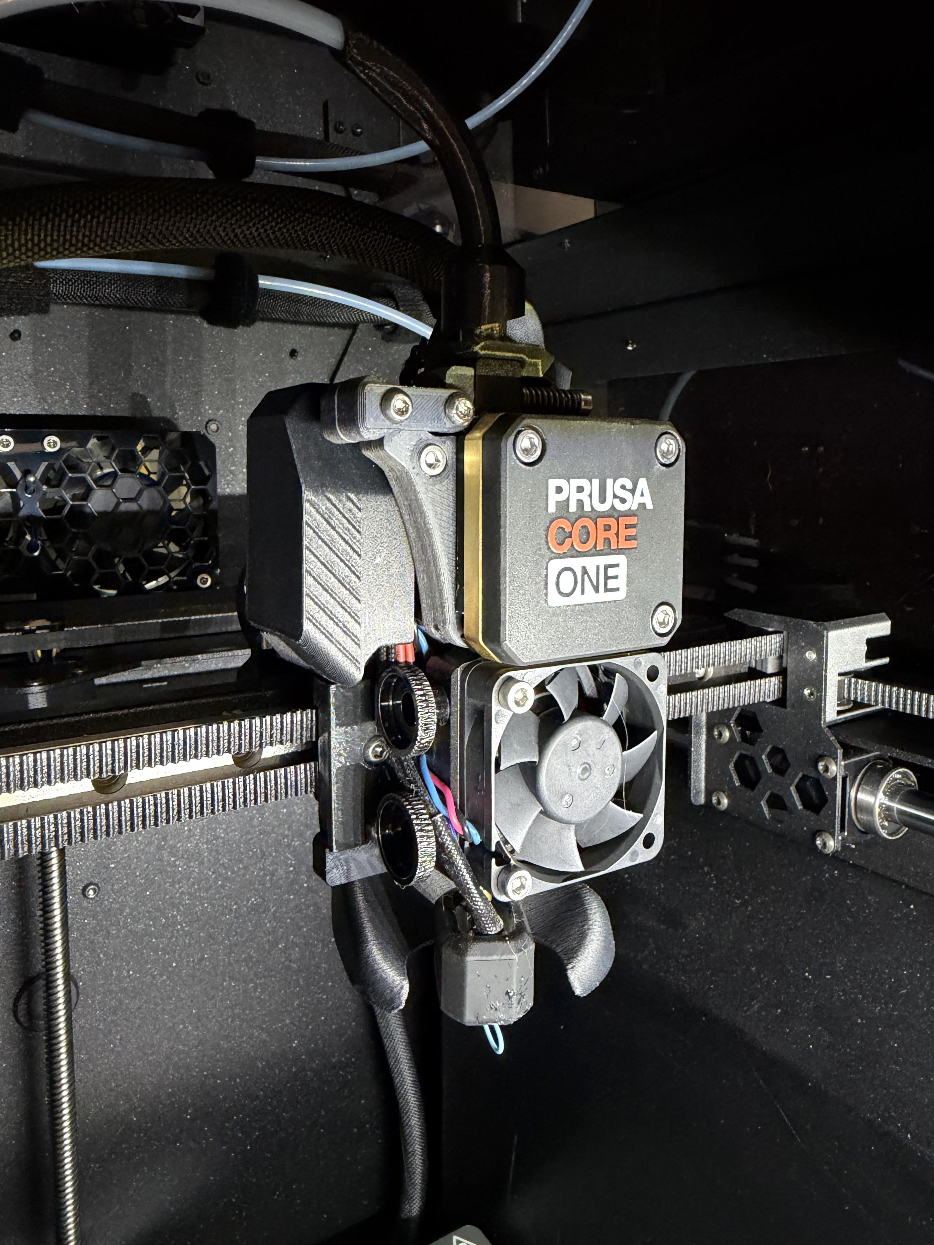
I used the HBridge in three contexts. To drive solenoids for the CNC Xylophone’s Mallets (3.4.6.1), we simply connect the solenoid as a DC load across two of the HBridge’s outputs. To drive a hobby servo (which uses a DC motor), we connect the HBridge as intended to the two motor leads, and can use the generic three-pin connector to read the servo’s position feedback encoder (which is a simple potentiometer). In the FFF 3D printers in this thesis (6.4.1 and 6.4.2), I use one leg of the HBridge to run the nozzle heater, the other half to run the Part Cooling Fan, the thermistor input to read the nozzle temperature, and I use the 5V that is exposed on the generic three-pin header to power the hotend’s cold side cooling fan.
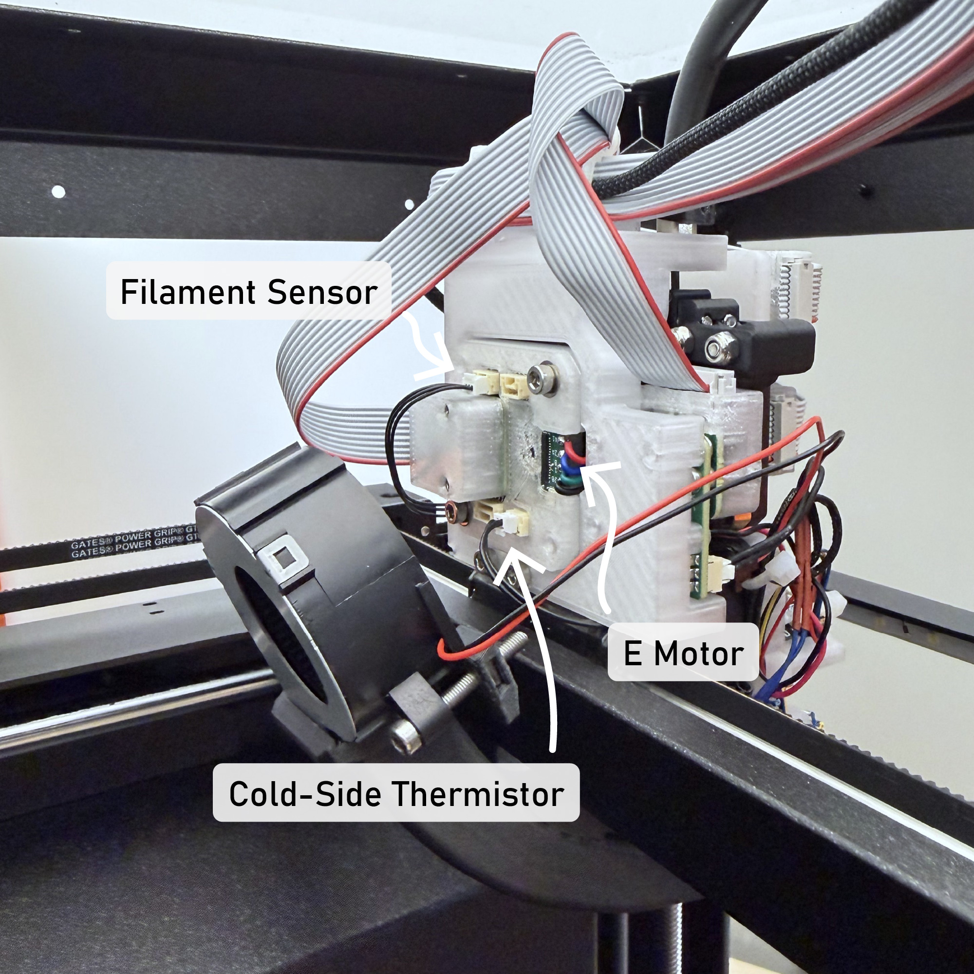
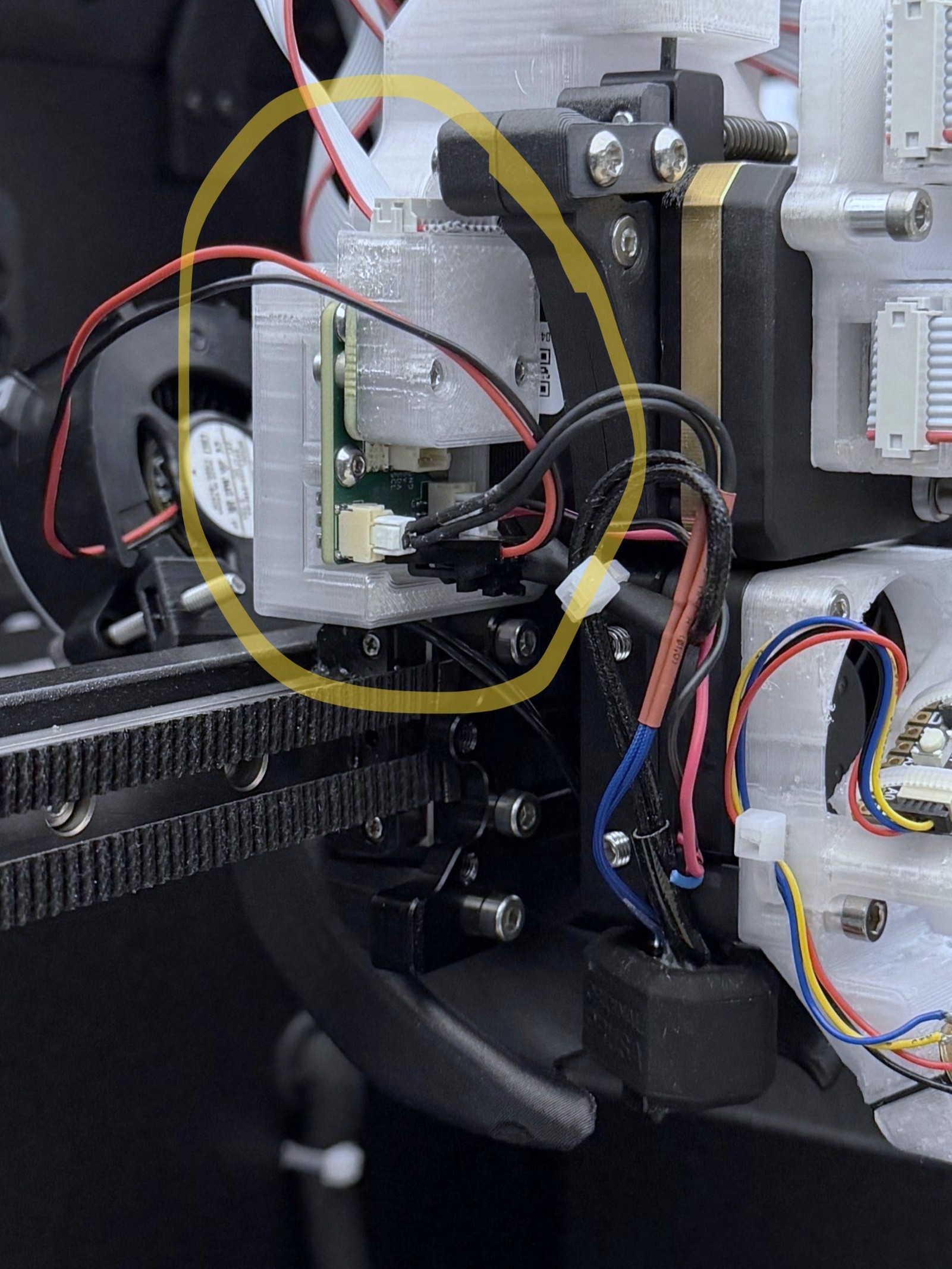
Because we define machines “across” firmwares, we can also mix modules’ functions across devices. For example the Prusa Core One, which becomes the FrankenPrusa in this thesis (again, 6.4.2) has a filament detection sensor (a GPIO, switch) and a hotend cold side thermistor (to detect heat creep). The HBridge, which I had tasked here to control the hotend peripherals, was out of spare connectors in this case - but I could simply wire those two sensors into the motor controller’s spare inputs. We can then easily rename these inputs in software to reflect their physical configuration. Again, this flexibility helps us to avoid developing new circuits while we go about building new machines.
I was able to use the Deadbugger in two contexts as well: to drive hobby servos as they are intended (through a PWM interface), and to control spare peripherals on the RheoPrinter: a line laser and an LED driver, both used for print inspection.
In some of these cases, we can write device firmwares to anticipate re-use, i.e. by keeping the firmwares themselves stateless - just exposing their low-level interfaces so that inputs and outputs to those interfaces can be configured or renamed appropriately in software. However, some require lower level changes. The simple solution to that issue at the time of writing is to modify the firmware for each new context, redefining the hardware as a new device. This is at least simpler than authoring an entirely new firmware, as the networking code and hardware layers are the same: we essentially just reconfigure the device’s API. This serves well enough and has been a productive tool during my time developing machine controllers, but in the future I would like to expand Pipes to enable on-the-fly reconfiguration of embedded codes using dataflow configurations as I discuss in Section 3.6.2 and as I explored in my masters’ thesis (Read 2020).
4.5.2 Retrofitting Machines
I used the Knuckles kit to control my own hardware, but also to retrofit the Prusa in Section 6.4.2. Besides allowing me to compare my printing workflow to the state of the art (6.10), it also gives us a one-to-one comparison in the practice of systems integration: an established product design vs. an ad-hoc assembly of modules.
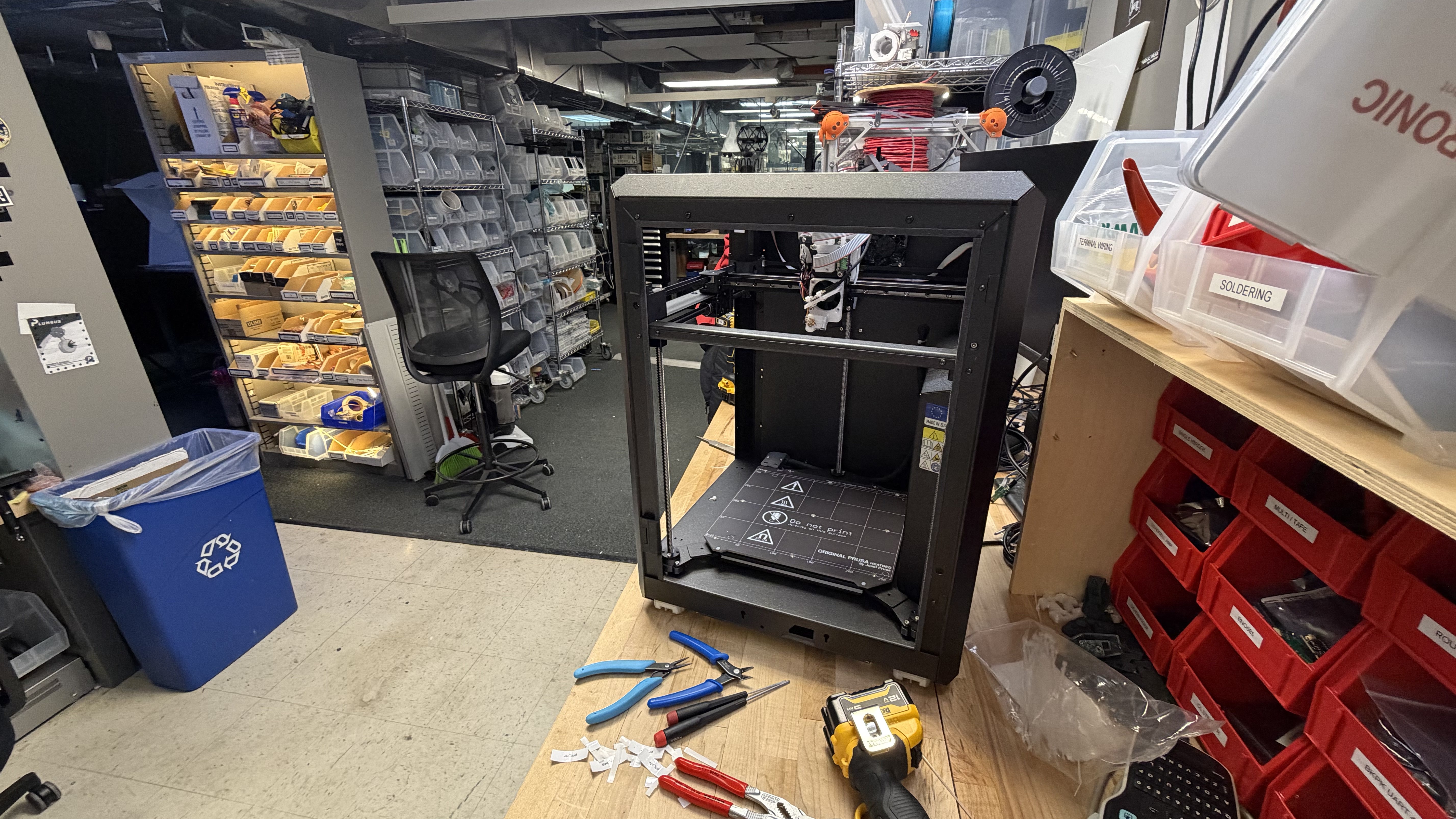
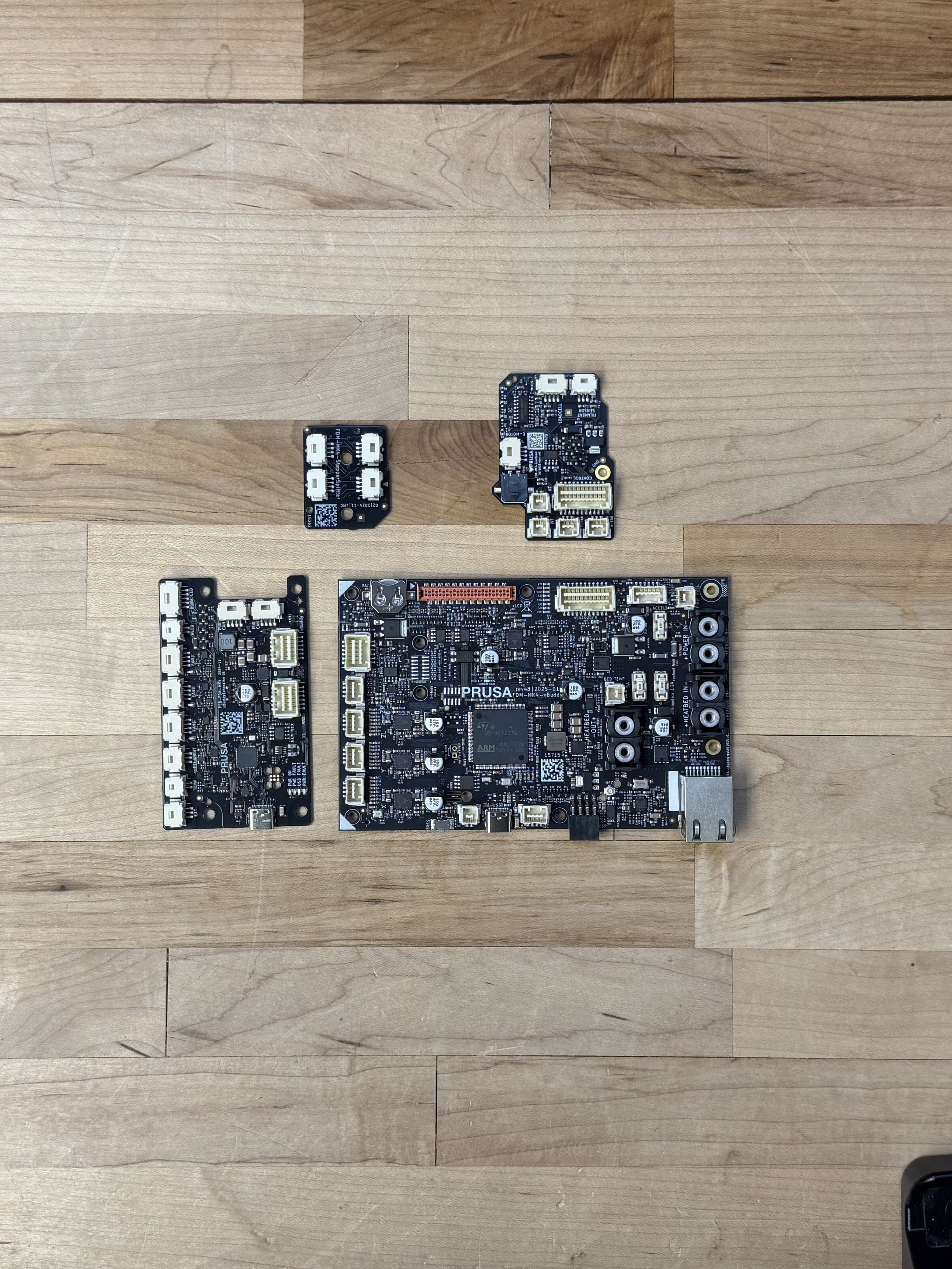
I was surprised that the modular set of controllers, which we would expect to mean overall more controller, is about equal on total board area. I think a lot of this has to do with wiring: most of the Prusa’s control board area is actually taken up by connectors. The same is true of ours. On two-sided boards especially, it is in many cases easy to saturate board area (and definitely board perimeter area) completely with the desired connectors; whereas IC’s and passive components continue to shrink, connectors cannot become vanishingly small because we need to manipulate them with our human-sized fingers, and because contact resistance of two metal blades has not fundamentally changed, leading to size limits that emerge from heat dissipation and management in power connectors.
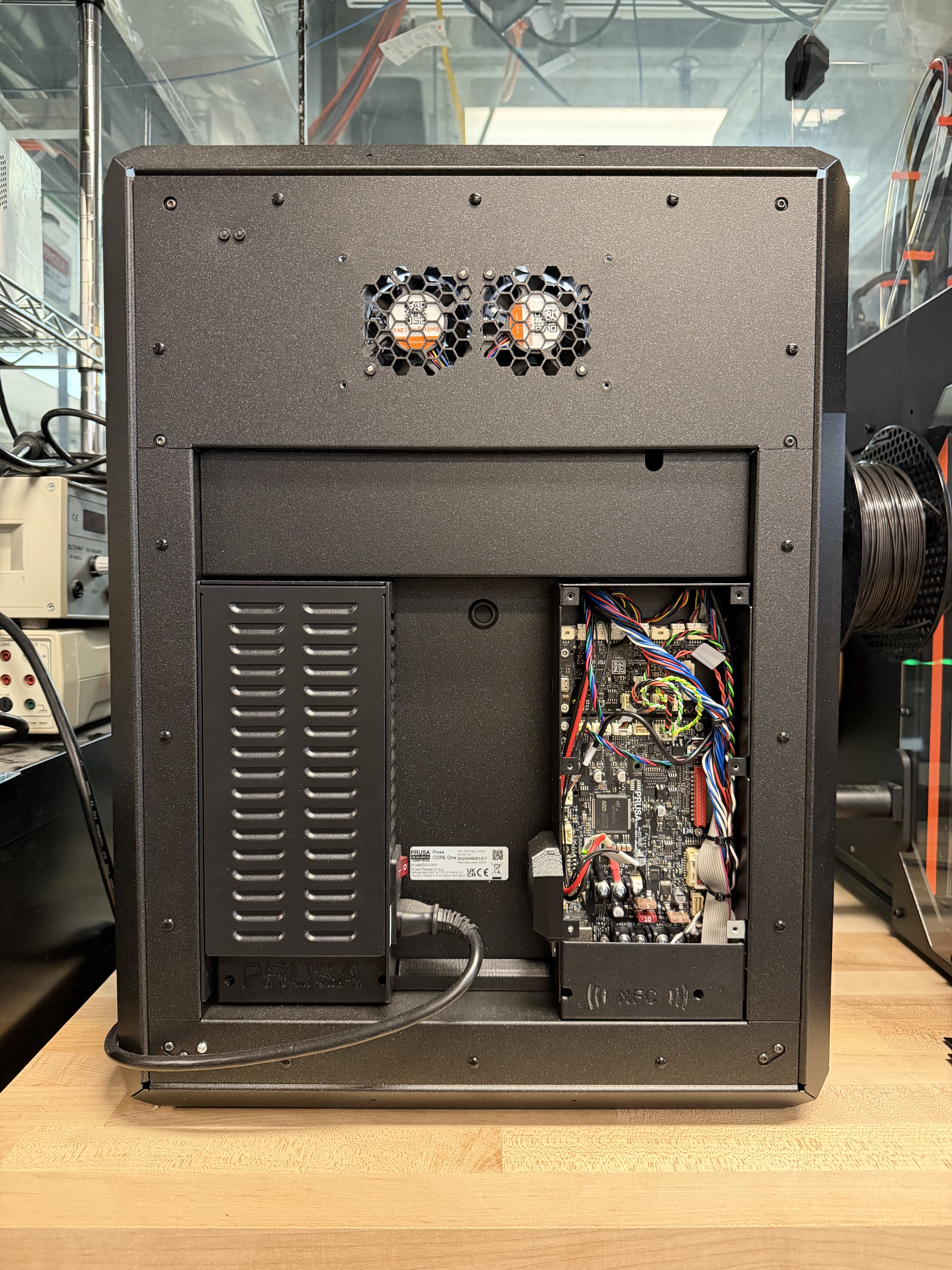
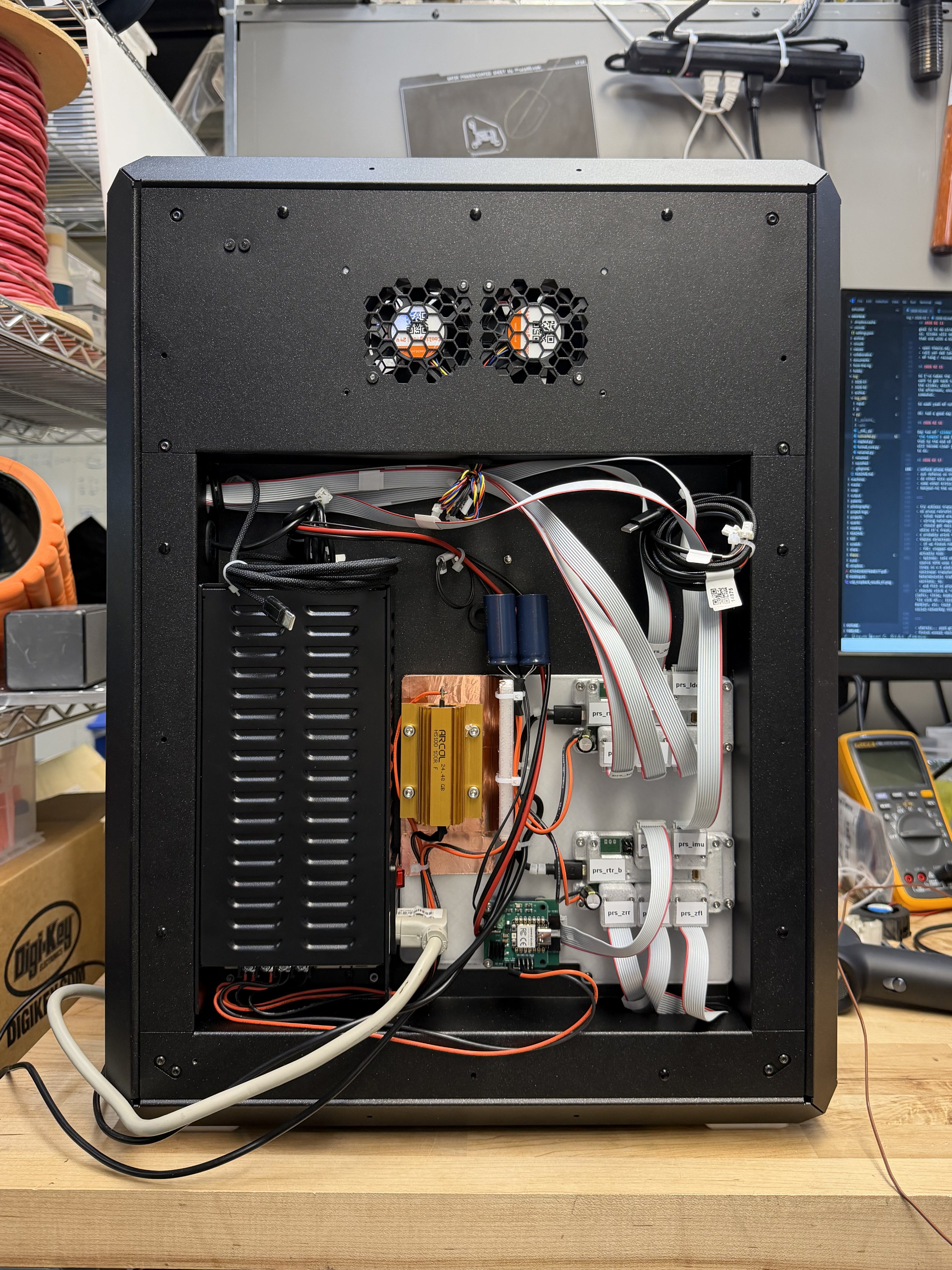
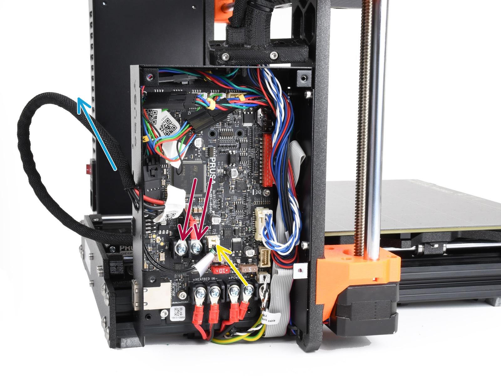
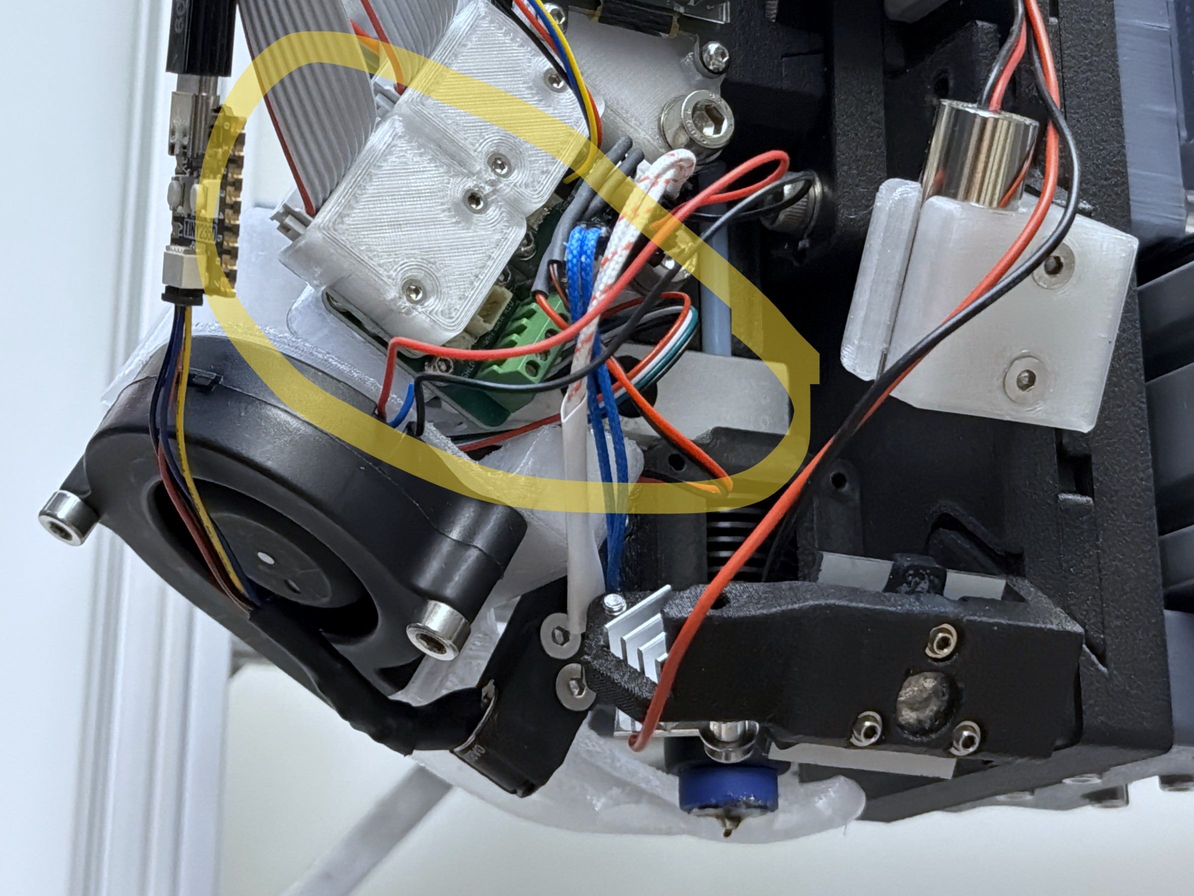
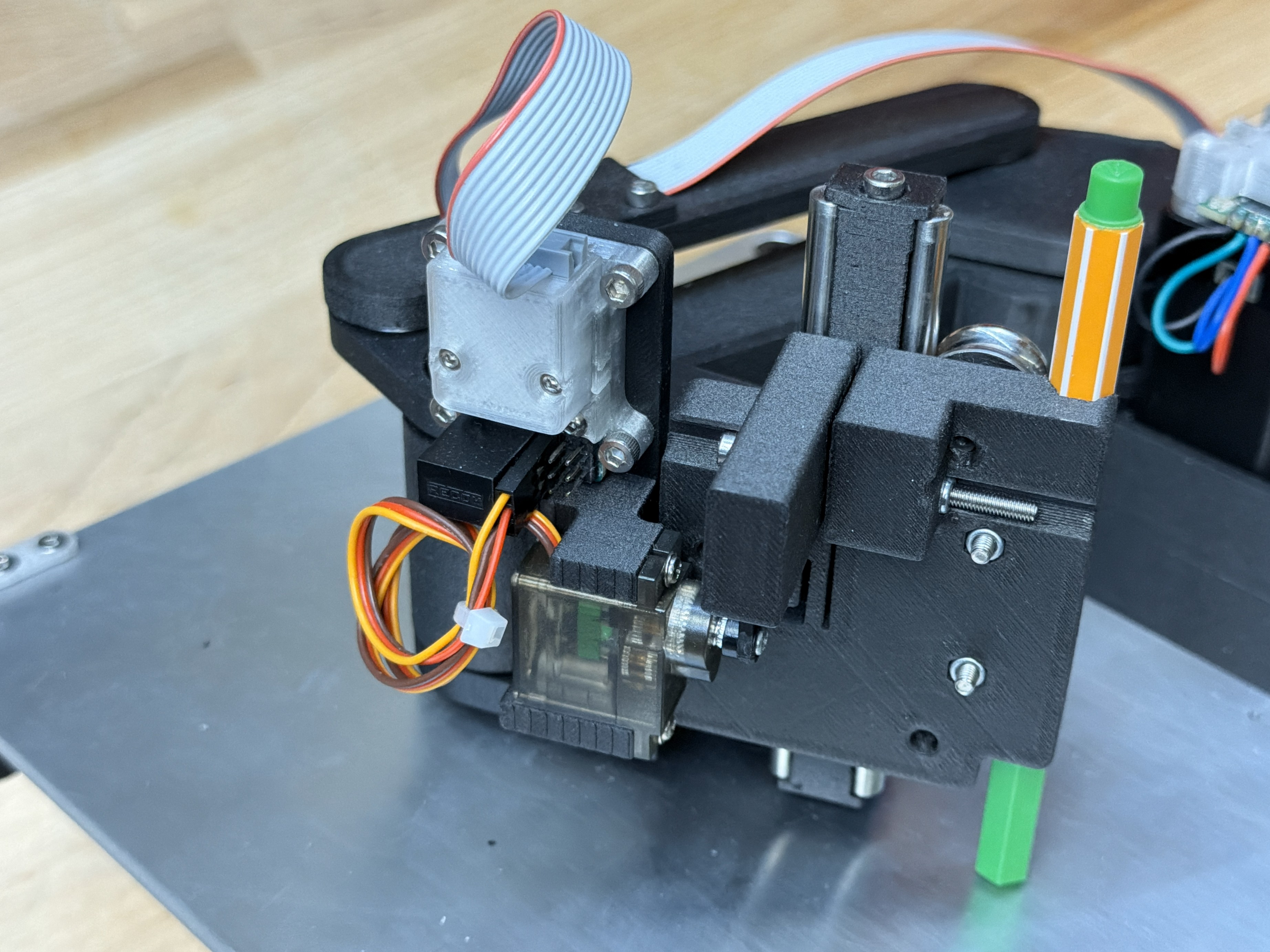
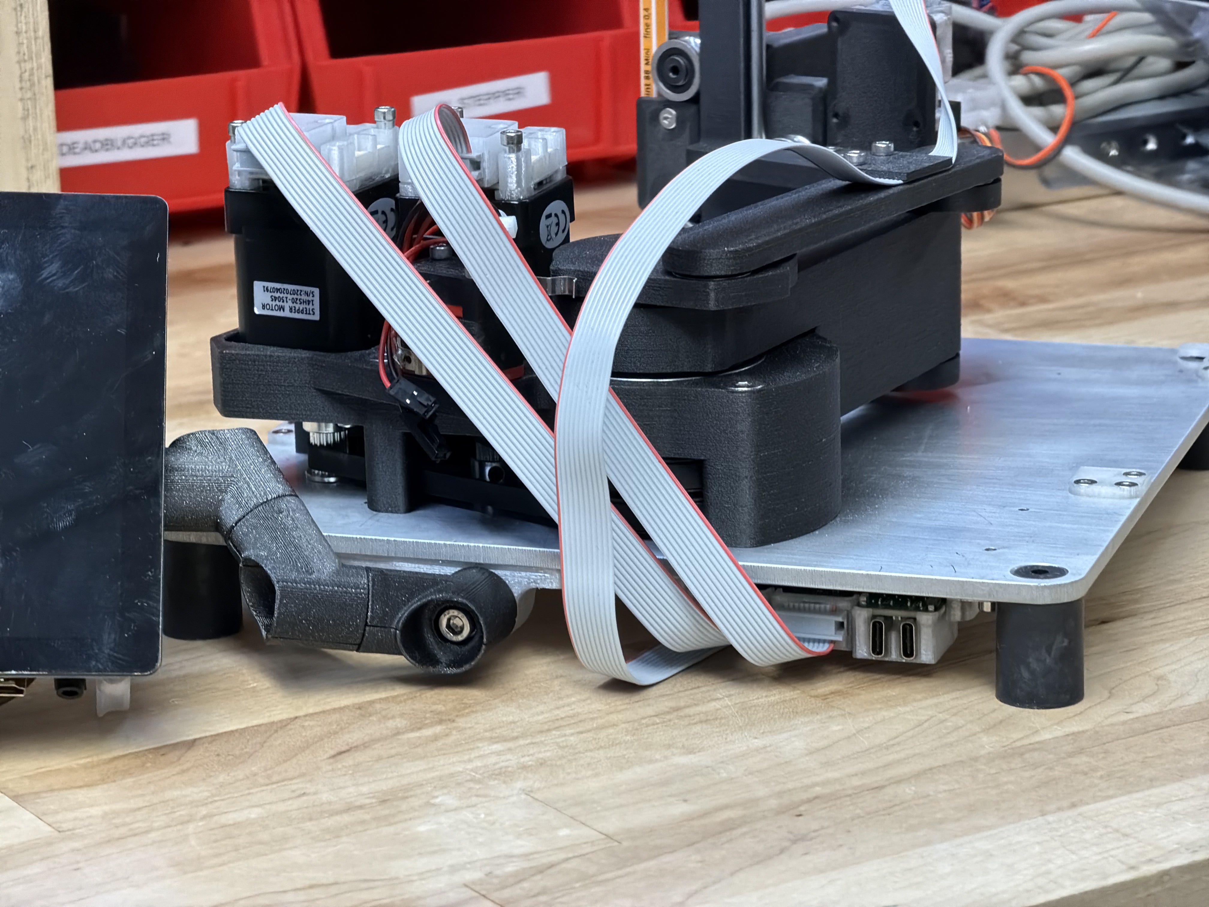
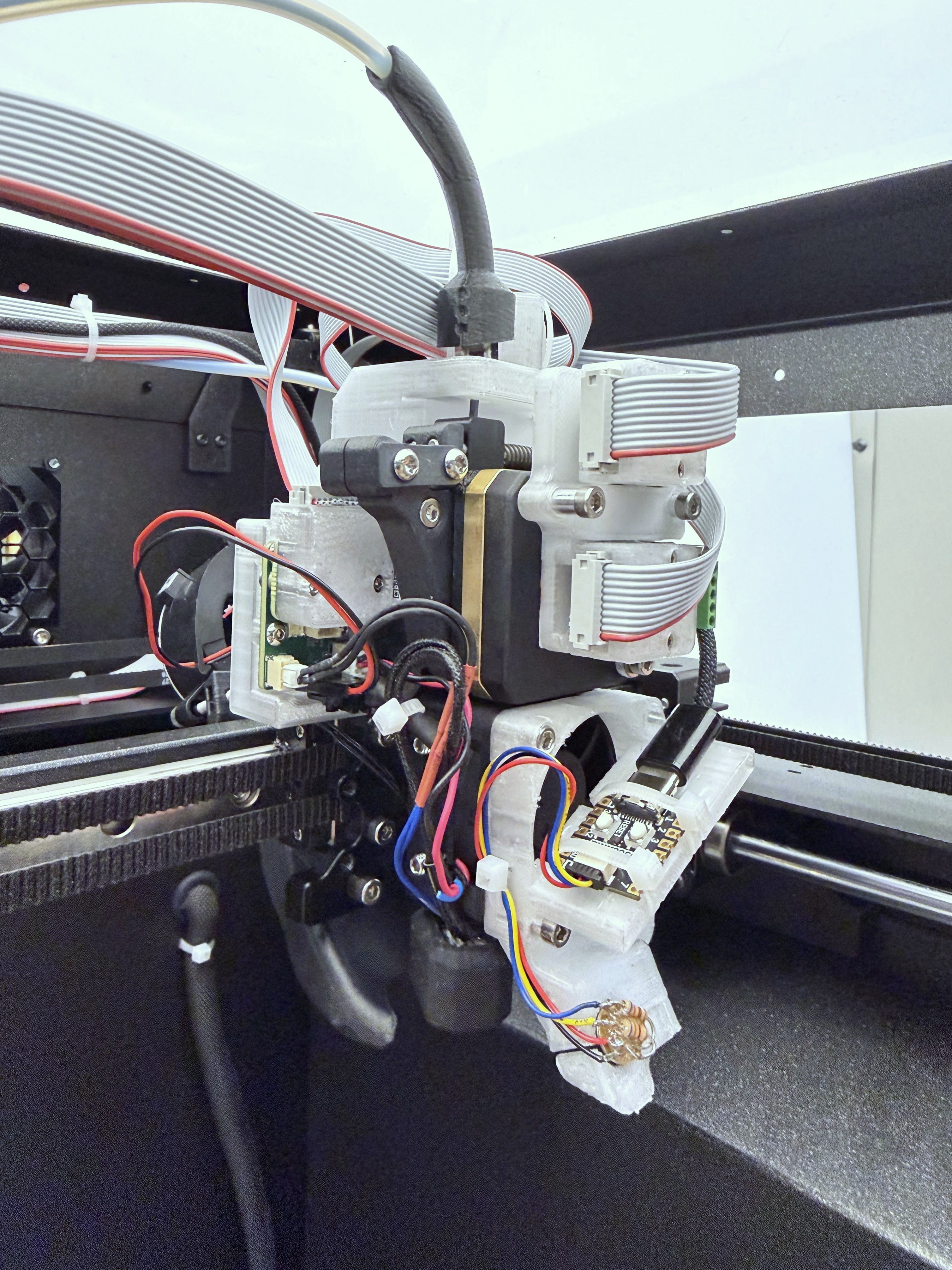
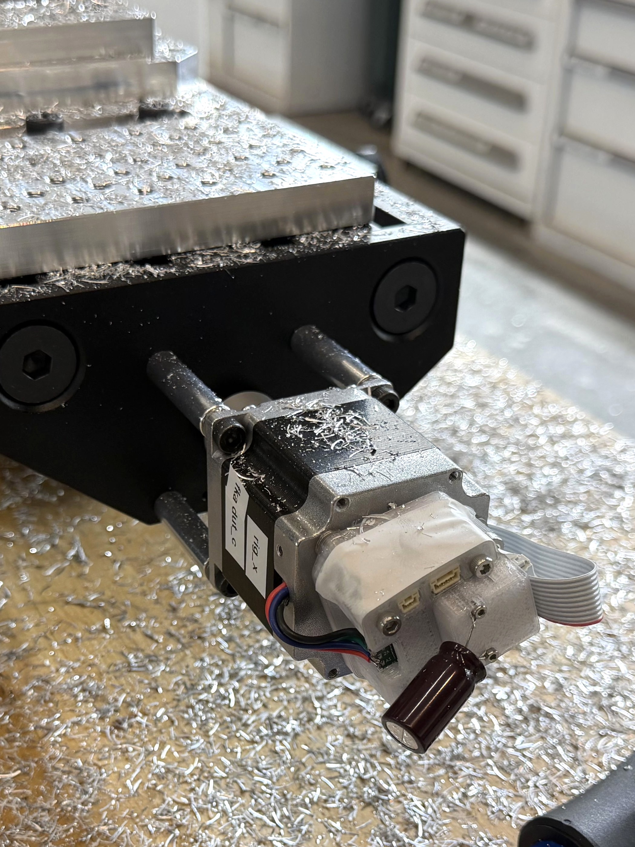
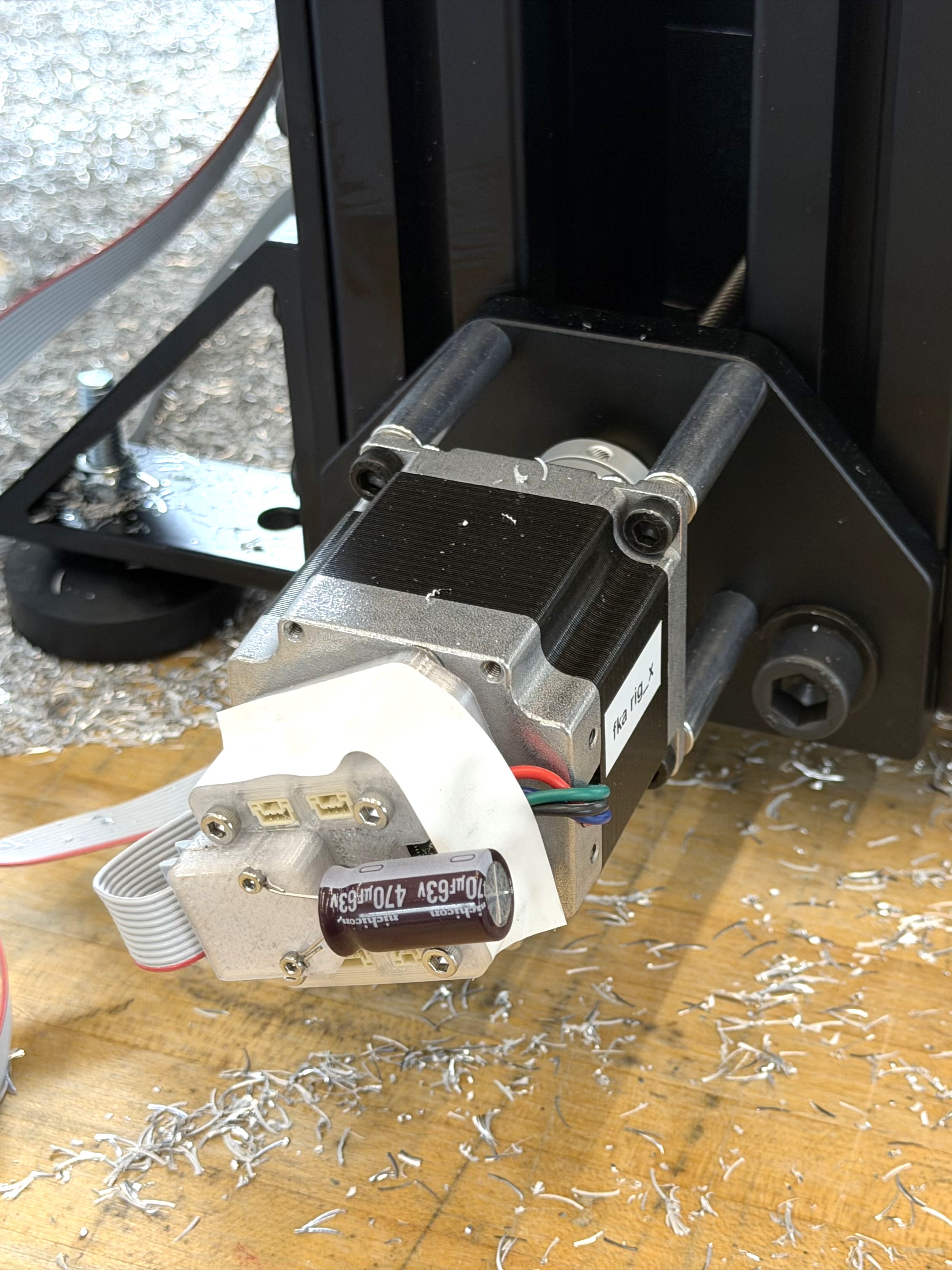
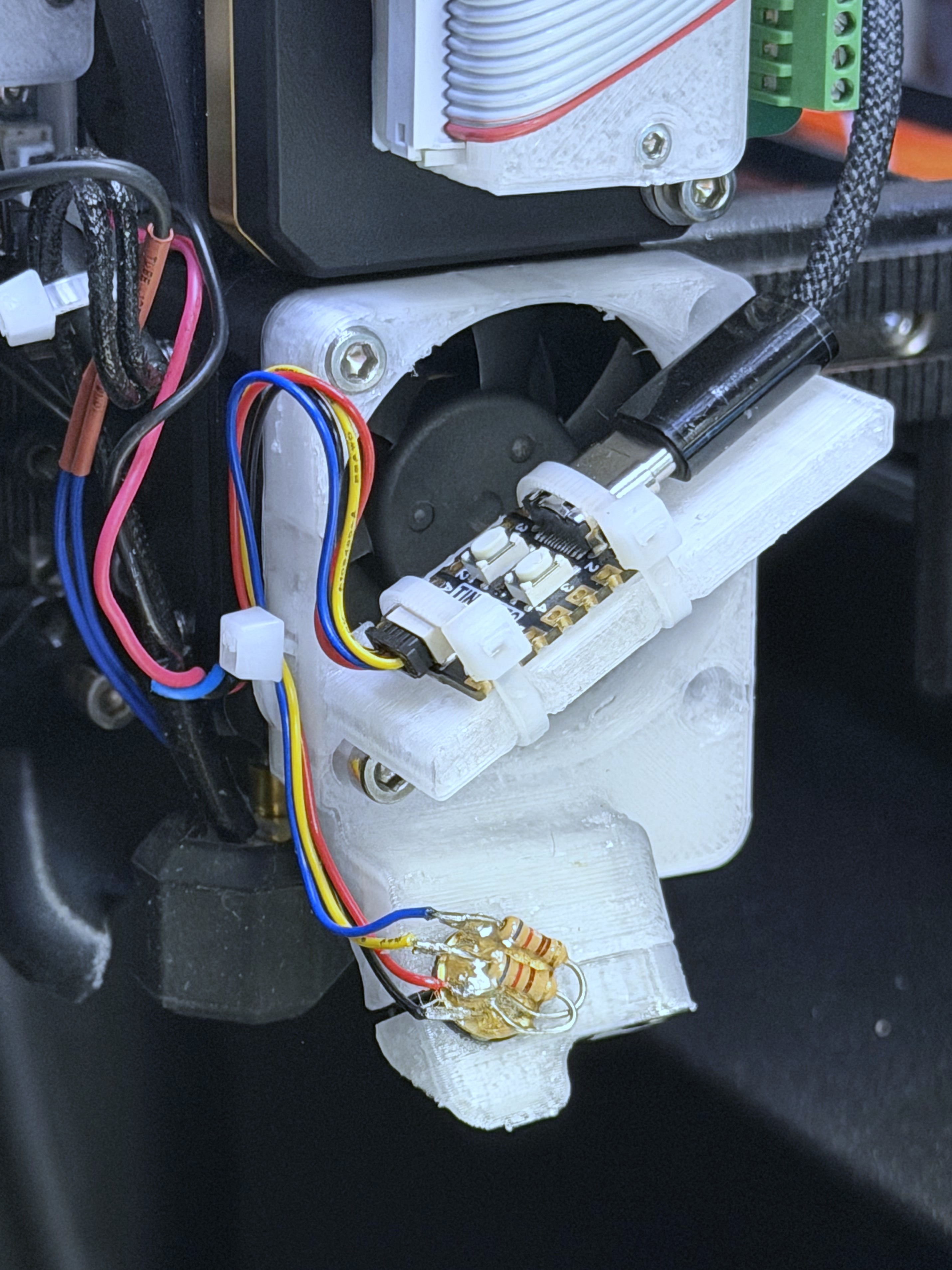
The rear end of the retrofit (above) is certaintly messier than the shipped product, but not eggregiously so. I added to their power supply a bleeder resistor (the orange aluminum block) and large bypass capacitance (blue cylinders), to help linearize the power into the FOC Steppers. The chassis wiring removed (below) is a much more heterogeneous set than in our retrofit, where a network connector lets us homogenize the main wiring harness. This is where IDC connectors and Ribbon Cables shine: we can easily make polarized, terminated cables of any length without the requirement for time-consuming and detailed work of wire crimping.
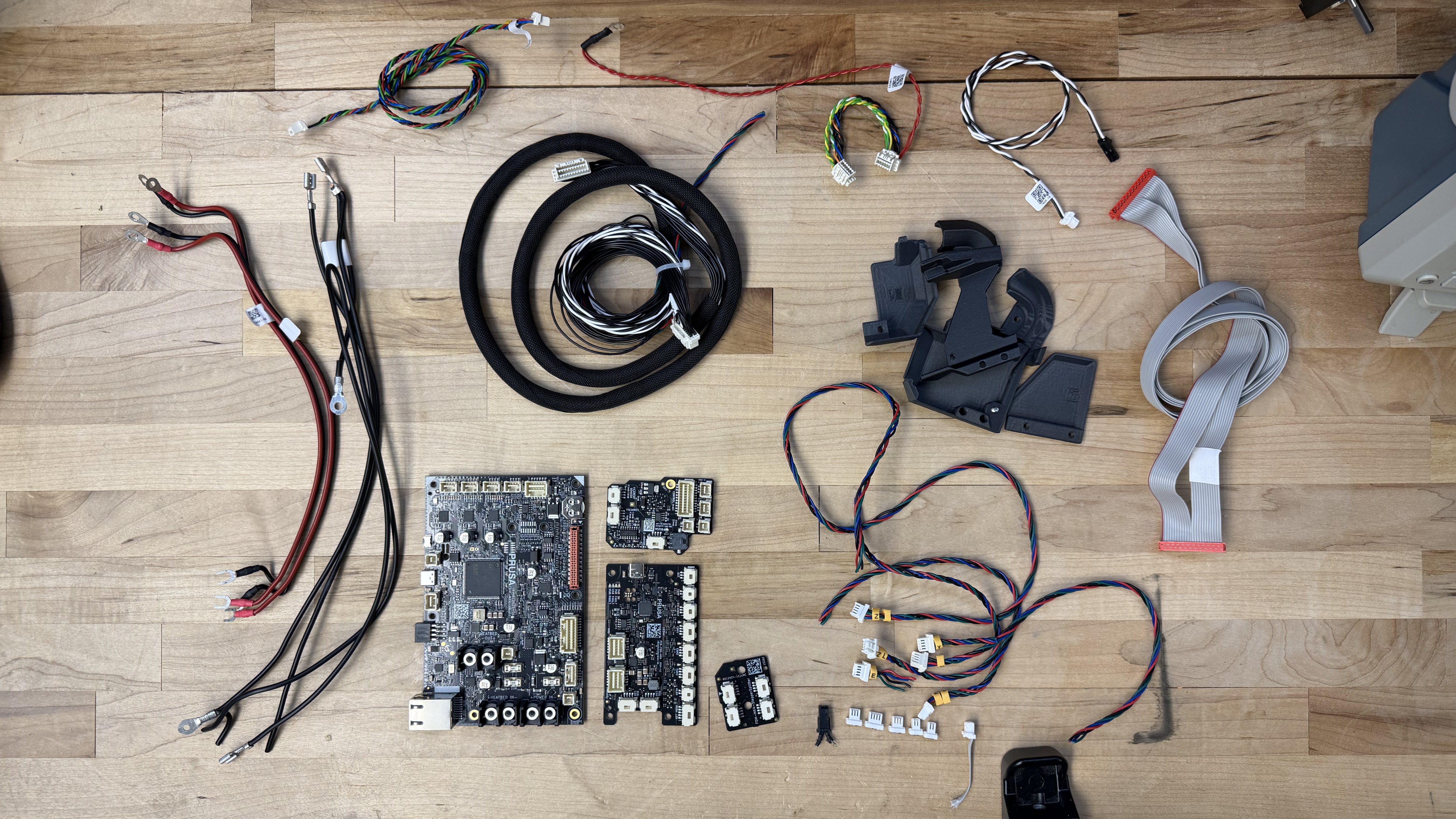
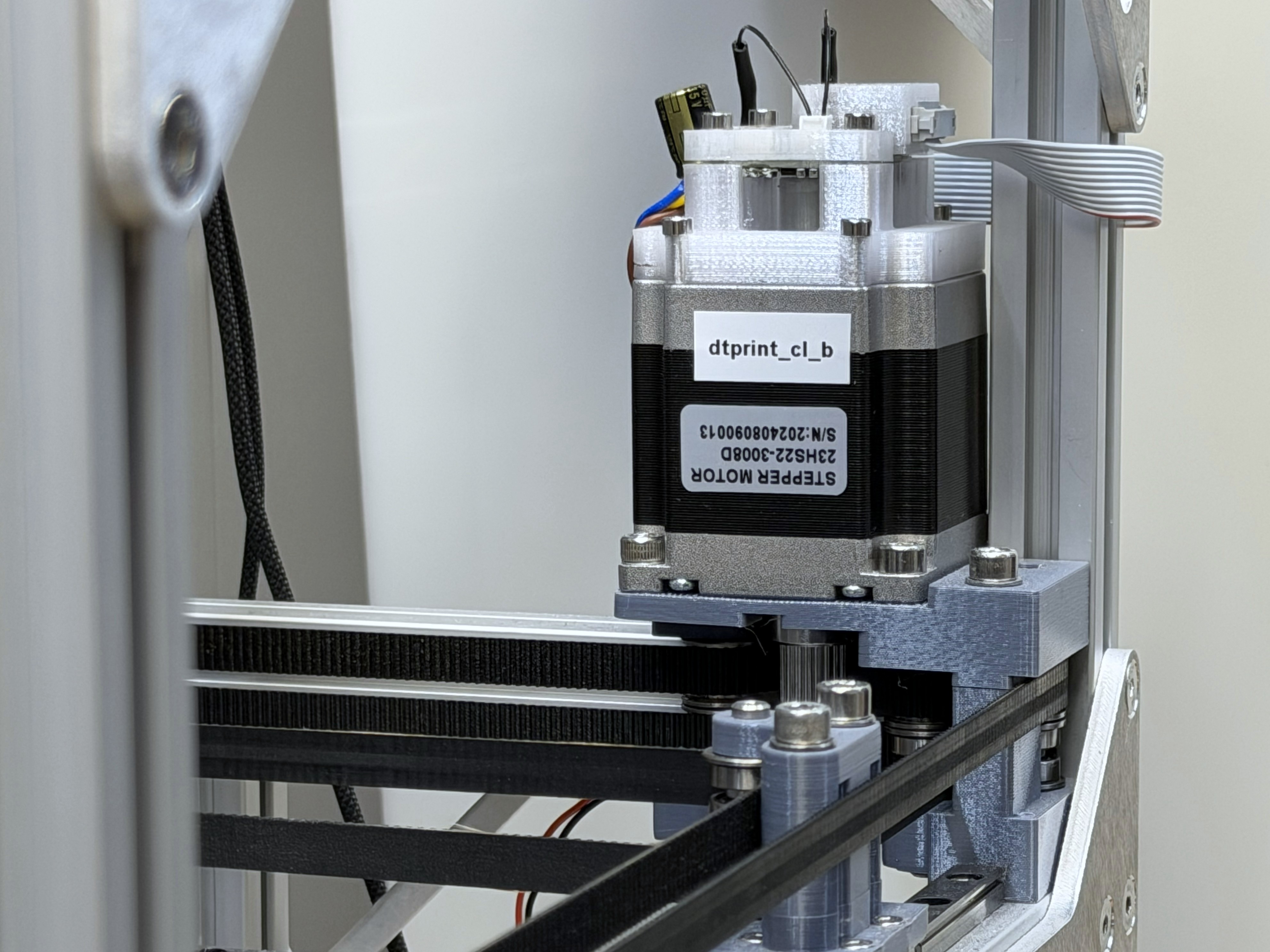
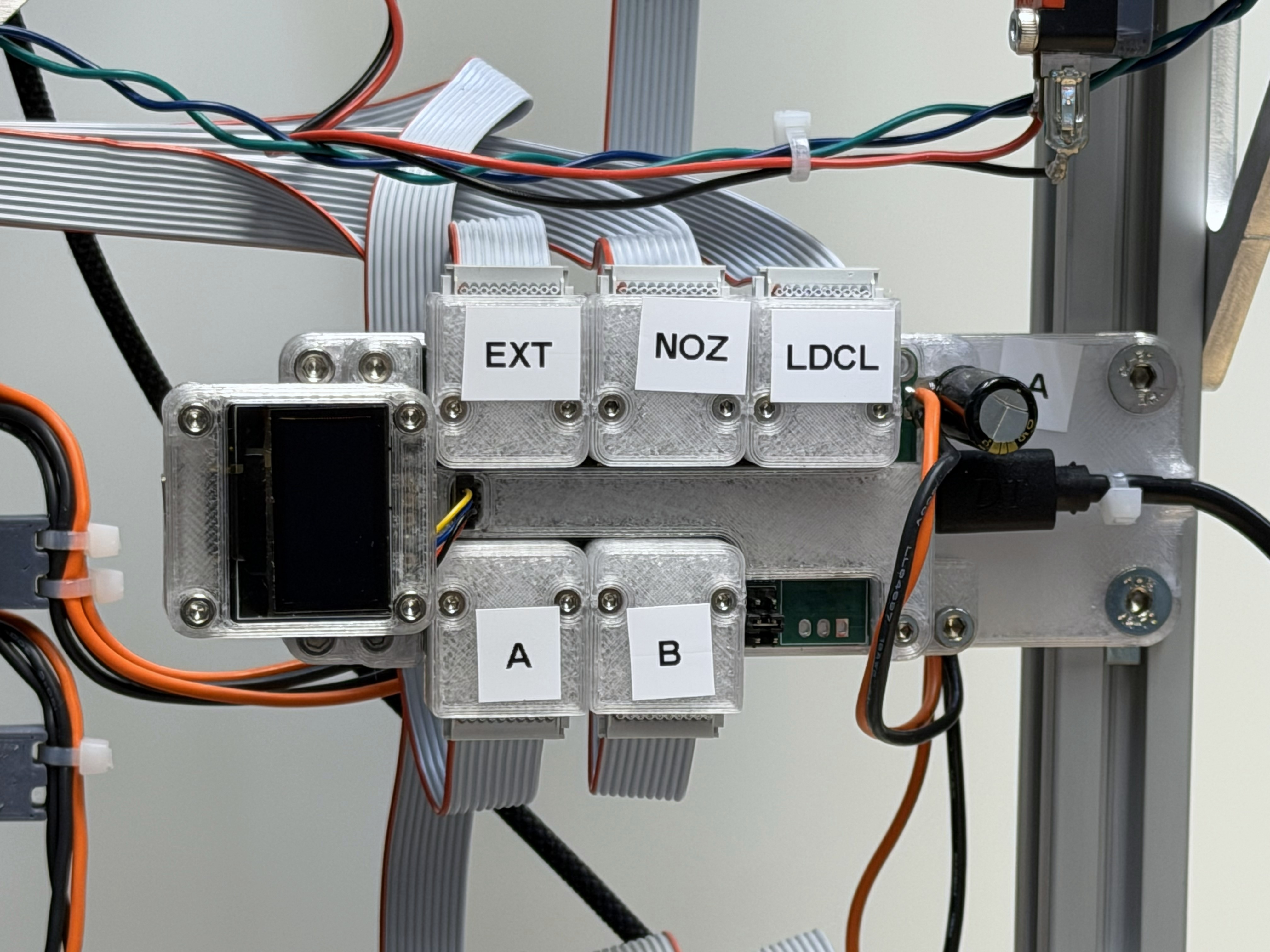
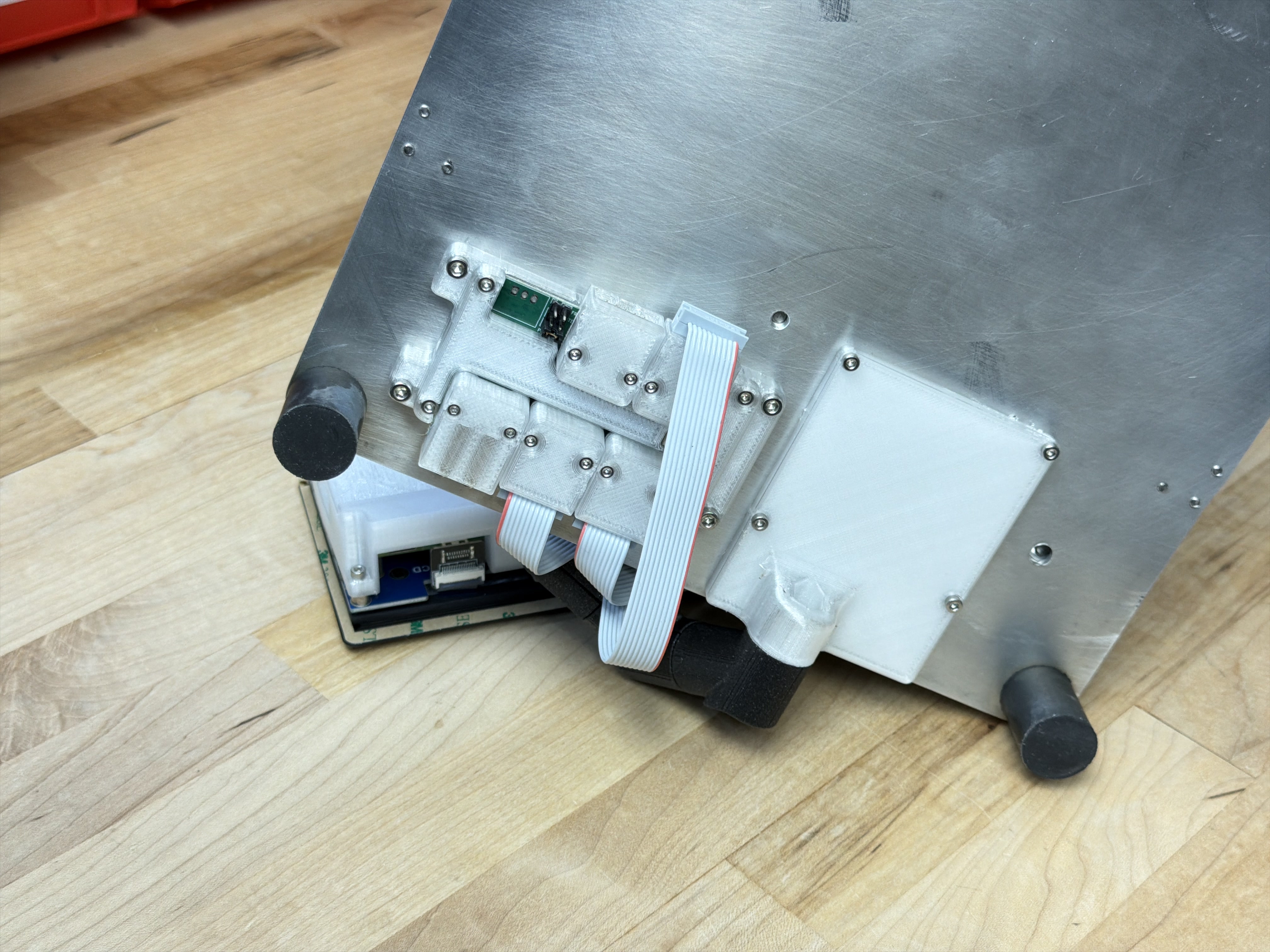
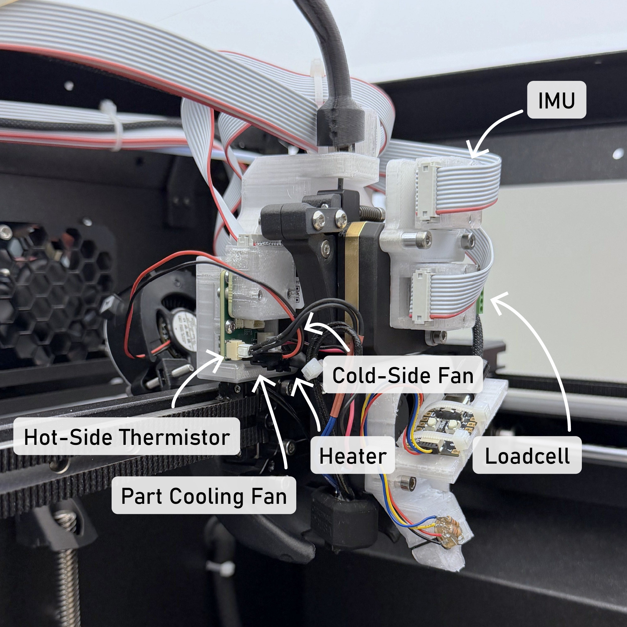
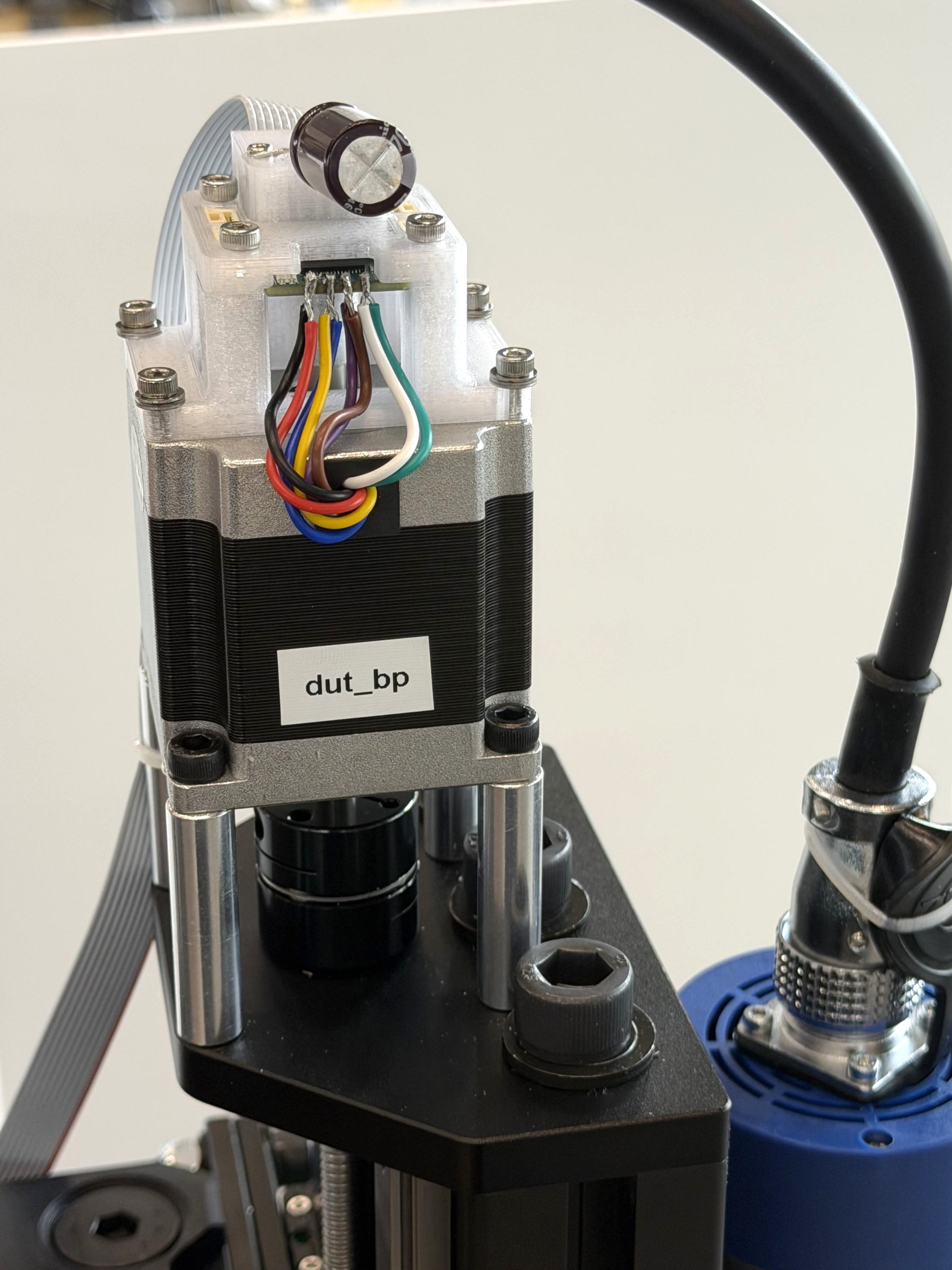
However, this practice takes for granted that we relocate the control circuits to where the relevant hardware is, as in Figure 4.18. We do not entirely remove the requirement for “terminal” wiring (connectors below), where our modules connect to the plugs and wires that are integrated into the actual pieces of hardware we are controlling.
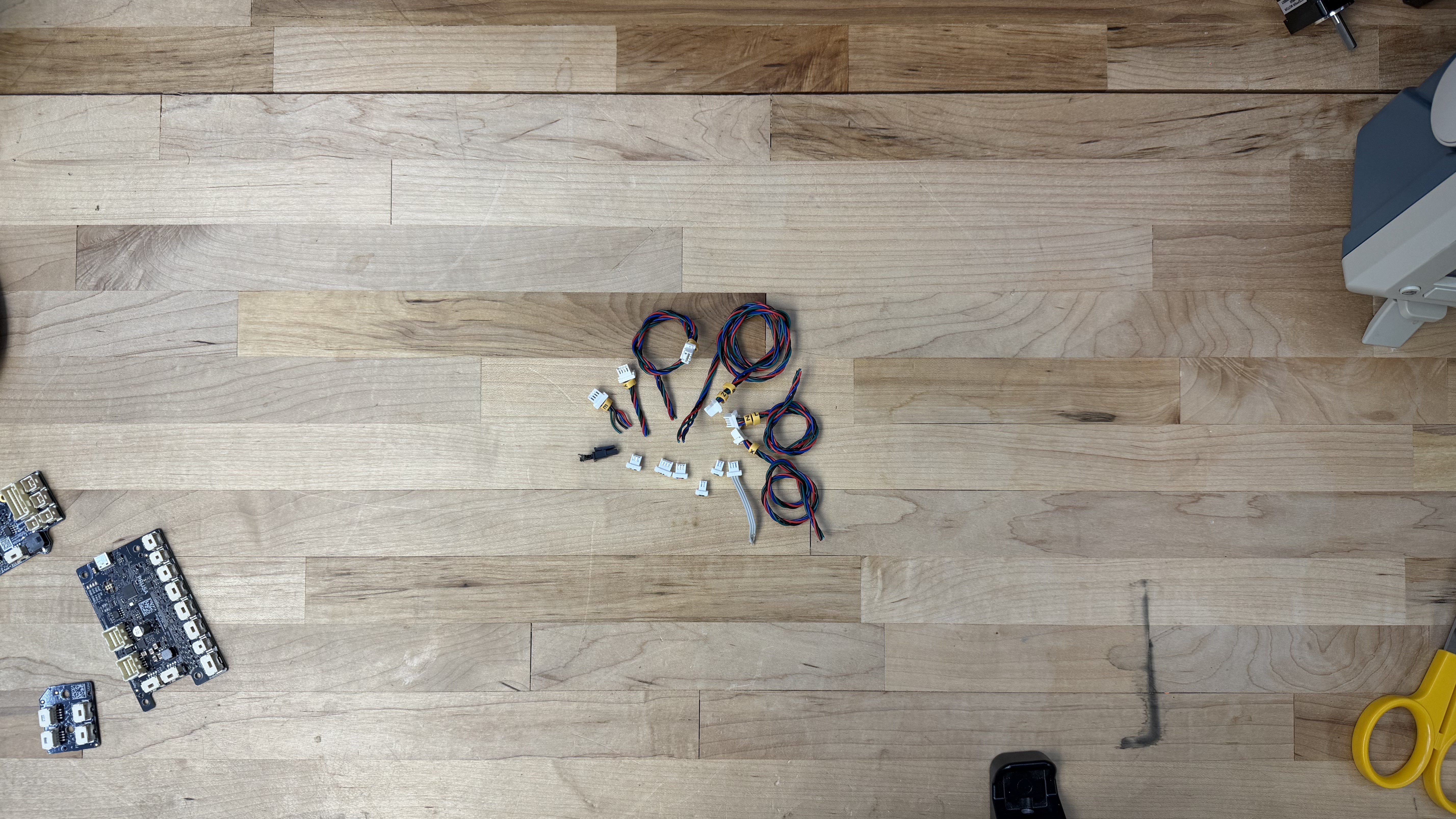
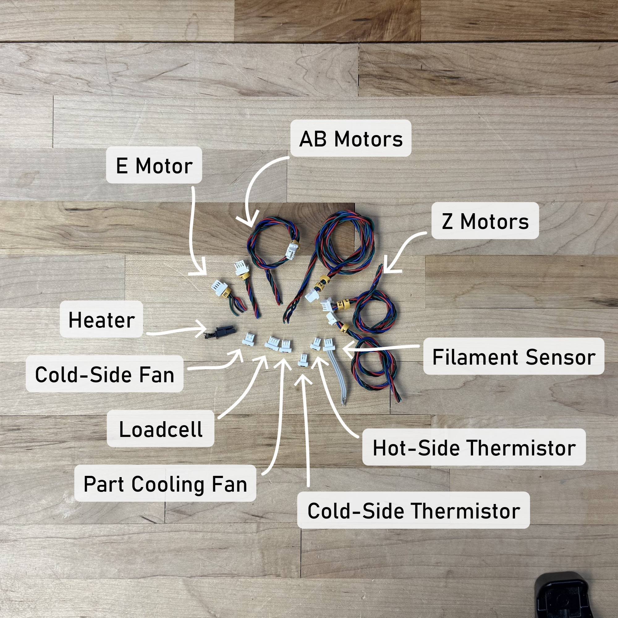
The actual electrical interface to the Prusa is quite thin: four connections to each motor, some heaters and thermistors, fans, and the loadcell. The Prusa (and our controller) doesn’t use limit switches, instead we simply run the servo into the machine’s hard stops.
The modular controllers let us take over the Prusa hardware with relative ease; I use their power supply and connect it to two Knuckles Hubs, which then each connect to motor controllers, heaters, etc. In all it took me about four days to dissassemble the Prusa, design some additional mounting brackets for my circuits, characterize motors (5.3.1), and then re-assemble it and begin printing (6.10.1). Were this step to require that I develop a new circuit board for the task, it may have taken up to two weeks to design that board, one or two weeks to wait for it to return from the fabricators, and perhaps another two weeks to write its firmware. In the case of the Prusa, this may have been easier because their hardware is open source - however, their control board does not have enough processing power for the requirements of this project, nor does it have inputs for motor encoders, or motor drive circuitry that can be used in a closed-loop manner.
I also used the Knuckles to control the CNC milling machine from Chapter 7. This system was much simpler than either of the printers, requiring only one Hub and three motor controllers. It also eschews limit switches in favour of homing via motor sensing. In this case, I did not instrument or control the machine’s spindle directly, mostly for lack of time.
4.5.3 About Hackable Systems
- There is an inevitability of unforseen requirements in systems assembly.
- We should aim to develop systems that can easily accomodate these ad-hoc inclusions, following the end-to-end principle.
- One error that I made in the design of the Backpack interface in this regard was not including breakout-board equivalents for either end of the interface: one that could mount to modules and let us solder ad-hoc networking technologies onto it, and another that could attach to the Backpack allowing us to integrate ad-hoc modules to our existing network links.
4.5.4 About Embedded Link Layers
- Many link technologies exist, each fulfilling their own niche.
- Support for these is limited in most microcontrollers, especially “heavy” links like Ethernet or CAN, which include large blocks of networking code.
- Co-processors are often used in these cases, where the device mcu is connected to said co-processor via SPI or UART.
- This introduces additional delay and overhead: it is effectively another link.
- Rather, it may be more productive to design simple software links, which add minimal code on top of ubiquitous mcu hardware like SPI, UART and I2C. These can be promoted to more robust signal levels using generic and (again, ubiquitous) technologies like RS485.
4.5.5 About Power Routing and Delivery
- In practice, routing power throughout a system can be as cumbersome as routing networks. For prototypes, it is valuable to have one-plug-for-both, see i.e. XT30+CAN devices that have emerged.
- In other systems, these concerns are often separated, since power and networking are both heterogeneous, collapsing those layers would require (again) more unique modules.
- It is a difficulty… especially because some devices are low power, others are extremely hot and dangerous. Providing a power management service within the knuckles ecosystem is a goal, but difficult to incorporate due to the breadth.
4.5.6 The Partitioning Problem, Again
In some ways, the arrangement of modular circuits and their wiring reflects the partitioning problem that I discussed in Section 3.1.1.
- Here, we mount modules close to the devices they control.
- In industrial systems, it is more common to co-locate all controllers in an enclosure on DIN rails, and build wiring looms from that enclosure to the hardware itself. Although there are of course cases (i.e. encoders and some other sensors) where the location of some circuitry alongside the relevant hardware is required.
- If we consider the observation that, in some cases, the circuitry required to integrate with a device becomes about as large as the connectors required to plug into it (4.5.2), locating controllers alongside hardware begins to make more sense - especially where tight integration reduces overall complexity. This would be driven by hardware component suppliers integrating their components with controllers.
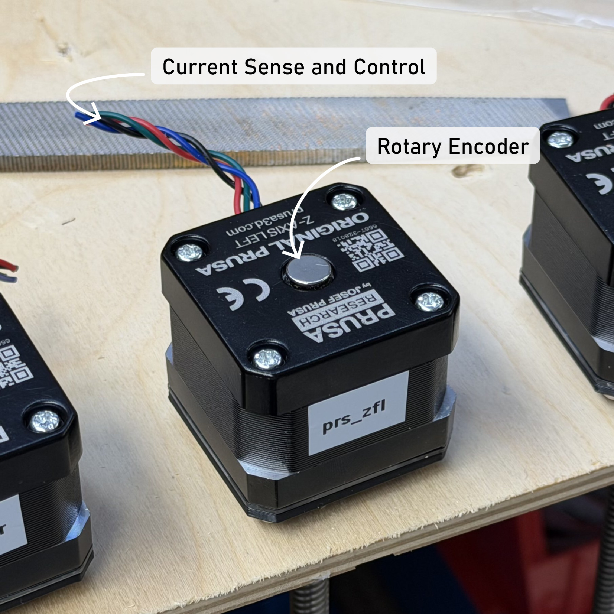
- Motors are the most common scenario, currently, where this is true: the device is quite large, and co-locating the drive circuitry with the hardware has the advantage of minimizing parasitic inductances and resistances that would otherwise exist in long cable runs between a servo controller and the servo’s stator coils. There is also - as mentioned - the issue of the encoder.
- There is some emerging practice of mounting electronics within connectors themselves, as in USB-PD cables that are electronically tagged to verify their current carrying capability (2021).