3 PIPES: Distributed Software for Systems Assembly
So far we have looked at why we want to build and modify machines using modular components Chapter 1, and then how I connect hardware and software modules to one another using OSAP Chapter 2. So, we can transmit bytes from module to module - and we can discover modules dynamically - but we don’t have a good framework for making sense out of those bytes. In the OSI model, this is layer six: presentation - which tends to merge with the application / software layer (seven).
In our applications, we want to accomplish two things. The first is to configure machines, i.e. make sense of which devices are in the network and connect them to one another according to some control logic. This means writing a kind of programming framework that includes a model of the network itself, and something not unlike the web browser’s DOM (document object model). Our second job is to task the machine, i.e. program it to do something / write a script or interface to operate the machine.
To accomplish these two tasks I wrote PIPES (for Piped Interconnect for Physical and Experimental Systems). Pipes runs with OSAP and is responsible for naming and describing software objects, building and modifying systems representations, building data flows between objects, and remotely calling software objects.
I already described the basic outlay in Section 1.5.1.2 - using a software representation of the system that combines network topology and software addressing, we can write scripts that configure dataflows and then operate them using function calls. In this section I will expand on the details; Section 3.1 explains how functions are exposed to Pipes, Section 3.2 explains how systems are represented and modified (Section 3.2.1), and shows code samples from a few systems (Section 3.2.2). Finally I evaluate Pipes on its ability to capture and represent an array of tasks, and on its performance Section 3.3.
- PIPES (systems assembly)
- graphs are a good representation for systems assembly because:
- make sense in distributed systems / across networks,
- include: networking between two embedded devices can be much faster than the same between two high-level systems: while the latter have more throughput, there are more layers (PCIE, OS, Language) between hardware (where the networking happens) and software in big systems, so a focus here is in developing networking where we can leave realtime in the realtime land, but still get insight (view, config) on the governing structure of those components
- can be super-duper fast (nothing to interpret, only to transmit)
- controls typically represented as flows, alongside many continuous tasks…
- make sense in distributed systems / across networks,
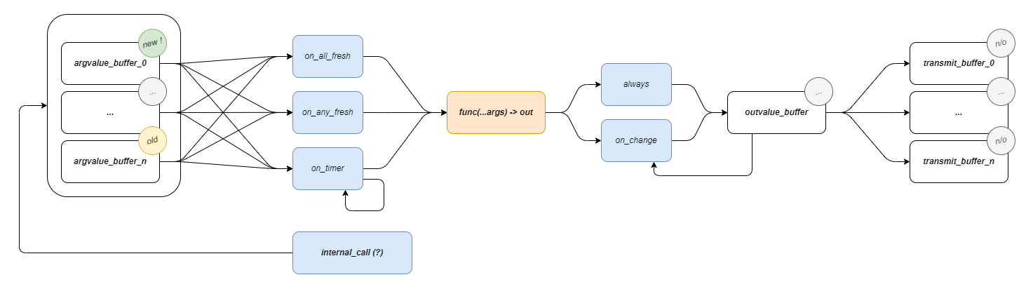
- functions can be made into graph blocks w/ (this pattern)
- contain logic for RPCs as well
- RPC calls as ‘heads’ for blocks of a graph,
- timers for continuous operation, gating for sync / wait / flowcontrol,
- tuple output -> tuple input for flows coordination, types conversion
- function signatures, types can be discovered,
- type conversion…
- this can be done automatically using template programming + metaprogramming,
- we can write proxies of any remote object by querying,
- proxies are handles in other software for configuration (piping) and for RPC calls / scripting,
- half-graph / half-script is a fruitful design pattern… we often want parts of both, or for them to work together, we don’t know when building firmware which is which, so we have generalized Functional Graph Component or whatever it is
- graphs are a good representation for systems assembly because:
3.1 Functions as a Basic Building Block
Functions become network interfaces, RPC and Dataflow. Some logic, some buffers, some serialization.
3.1.1 Automatic Generation and Discovery
Pipes functions can be discovered remotely, meaning that if I develop an embedded device with a particular set of capabilities, anyone can plug it into their system and read it’s capabilities from the device - bypassing a requirement to read docs or APIs, craft interface code, and hope that my representation of the device matches to yours - this is all done automatically.
- going from user-code to system-object is tricky,
- but it’s important that we can do this, since we want to grow this commons, so it needs to be easy to put new things in the commons…
- everyone knows how to write a function
- so, herein, we try to use metaprogramming (code that looks at code) to ingest functions as objects of our system’s making…
In (Eghbal 2020) (Benkler, Shaw, and Hill 2015) (Lerner and Tirole 2002) and (Hess, Ostrom, and McCombs 2008), operations and economics researchers studying the success of Open Source Software note two key properties: existing modules should be easy to integrate into new systems, and new modules should be easy to generate and add to the ecosystem. Basically, using components of the ecosystem should be straightforwards, and generating new components should be just as simple. (Benkler 2002) in particular notes that “In order for a project to be susceptible to sustainable peer production, the integration function must be either low-cost or itself sufficiently modular to be peer-produced in an interative process.”
The controllers developed in this thesis are distributed systems comprising both low-level firmwares and high-level planners / controllers. For those to work together, they need properly articulated software / network interfaces, i.e. they need to be easy to integrate with one another. Since I have been building all of the modules themselves, it also serves me well if they are easy to generate; I have had a good toy problem for the broader context.
In the state of the art these integrations are maintained by hand: distributed systems are ‘authored’ twice (once during setup and again as a reciprocal code structure). GCode is effectively the same: new codes are added in firmware (by machine control developers) which are then written down as specs and communicated to CAM developers. In the Appendix on GCode Representations I work up an example of how one GCode is authored in firmware, then as a specification, and how it is used in a program (to compare to the workflow in the listings below). The inevitable misalignments that arise cause hard-to-diagnose errors, and the duplication of efforts wastes time during machine development (and makes it more costly to iterate or update designs).
In OSAP, I contribute presentation layer codes that automatically generate these intermediary representations. These codes allow firmware developers to turn any given function call on their device into an RPC (remote procedure call), a common type of interface in distributed systems. RPCs are effectively functions that are implemented on remote devices that can be called from some other device. The following listings work through an example of using one of these RPCs.
float readAvailableVCC(void){
  const float r1 = 10000.0F;
  const float r2 = 470.0F;
  // get the analog reading (int)
  uint16_t val = analogRead(PIN_SENSE_VCC);
  // convert to voltage,
  float vout = (float)(val) * (3.3F / 1024.0F);
  // that's at 10k - sense - 470r - gnd,
  // (vout * (r1 + r2)) / r2 = vcc
  float vcc = (vout * (r1 + r2)) / r2;
  return vcc;
}

// use BUILD_RPC macro
// to transform into pipes function
BUILD_RPC(readAvailableVCC, "", "");BUILD_RPC() macro to rollup any given function (with some limits on argument and return types) as a remotely callable (and discoverable) function.
# auto-generated proxy,
class HBridgeProxy:
  # ...
  async def read_available_vcc(self) -> float:
      result = await self._read_available_vcc_rpc.call()
      return cast(float, result)
# ...async def main():
system_map = await osap.netrunner.update_map()
hbridge = HbridgeSamd21DuallyProxy(osap, "hbridge_dually")
await hbridge.begin()
# turn it on
print("... request voltage")
await hbridge.set_pd_request_voltage(15)
print("... await voltage")
while True:
vcc_avail = await hbridge.read_available_vcc()
print(F"avail: ${vcc_avail:.2f}")
if vcc_avail > 14.0:
break
print("pulse...")
for _ in range(100):
print("...")
await hbridge.pulse_bridge(2.0, 1000)
await asyncio.sleep(1.75)
await hbridge.pulse_bridge(-1.0, 50)
await asyncio.sleep(1)
print("... done!")The BUILD_RPC macro uses c++ template programming to generate a wrapper class around the provided function that provides network handles to it, that enables other devices on an OSAP network to query the function for its signature (to learn its name, return type, and argument types), and to call it remotely. OSAP also includes a network discovery routine (to find, name, and address modular devices). Using these two together, we can automatically generate a the interface codes (proxies) required to interface with whatever hardware is connected on the network.
To evaluate success on this front, I develop and deploy automatic proxy generation codes in the machine systems discussed in this thesis. I will also use them with a group of machine builders in the plotter comp to generate motion systems. These interfaces can be evaluated quantitatively for performance at runtime (incurring minimal compute or space overheads) and at compile time (minimal overhead program size), and they can be evaluated qualitatively on many fronts:
- They should be able to describe most of the breadth of descriptions possible with ‘normal’ programming (i.e. most common data structures).
- They should be consistent, reliable and require minimal programming overhead (burden on the programmer, not the computer) to deploy and ingest.
- They should be flexible across many use-cases.
- They should be descriptive enough so that they can be used with little documentation (or should contain accomodation for documentation).
- They should be easy to interrogate and modify: where the interface inevitably break down, or a lower-level of description is needed, that should be available.
3.2 Combining Dataflow with Scripting
we want to make dataflows for high-speed, determinism, and remote low-level loops, … we want scripts to configure / control / task it all together
3.2.1 A Systems Object Model
Like the DOM, but for hardware. Devices, Instances, Functions… Pipes.
3.2.2 Examples from a Pipes Machine
Code Snippets here are dropped-in from elsewhere and out of date.
In the paradigm introduced in this thesis, the same program as presented above in Listing 1.1 is a ‘real’ program (a python script) rendered in Listing 3.4, and the homing subroutine is available for inspection Listing 3.6.
Machine kinematics are represented and modified in MAXL (Chapter 5) using modular blocks of code (see Section 5.3.2 and Section 5.5.1) that enable machine builders to write and edit their controllers’ kinematic chains without re-compiling firmwares and simulate them using digital twins.
… i.e. here we should show how the machine is configured using blocks (manager.connect), and then used w/ the scripting API, … this is going to ~ concide with our look at pipes later, but we can kick it off with this
await machine.home()
machine.set_current_position([110, 120, 30])
await machine.goto_now([10, 10, 10], target_rate = 100)

await spindle.await_rpm(5000)

await machine.goto_via_queue([10, 10, -3.5], target_rate = 10)
await machine.goto_via_queue([20, 10, -3.5], target_rate = 10)
await machine.goto_via_queue([20, 20, -3.5], target_rate = 10)
await machine.goto_via_queue([20, 10, -3.5], target_rate = 10)
await machine.goto_via_queue([10, 10, 10], target_rate = 10)

await spindle.await_rpm(0)

await machine.goto_now([110, 120, 30], target_rate = 100)await machine.route_shape(svg = "target_file/file.svg", material = "plywood, 3.5mm") async def home(self, switch: Callable[[], Awaitable[Tuple[int, bool]]], rate: float = 20, backoff: float = 10):
# move towards the switch at <rate>
self.goto_velocity(rate)
# await the switch signal
while True:
time, limit = await switch()
if limit:
# get the DOF's position as reconciled with the limit switch's actual trigger time
states = self.get_states_at_time(time)
pos_at_hit = states[0]
# stop once we've hit the limit
await self.halt()
break
else:
await asyncio.sleep(0)
# backoff from the switch
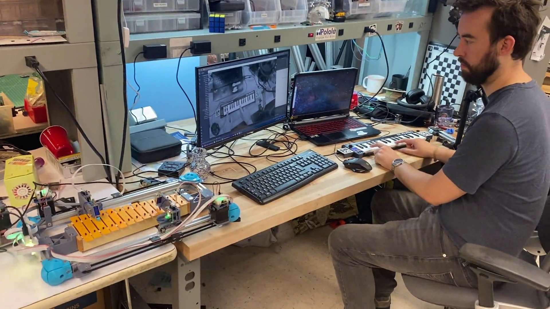
await self.goto_pos_and_await(pos_at_hit + backoff)Our codes are longer because they embed more information, and they are semantically meaningful - for example, I haven’t had to use comments in the scripts above because the function names themselves are human-readable. We can also easily describe dynamic or interactive controllers in this paradigm, as is the case with the example below (Figure 3.4 and Listing 3.7), where we use CV in conjunction with MAXL to ‘play’ a robot xylophone.
  async def handle_echo(reader, writer):
      print("Connected")

      stop_requested = False
      while True:
          data = await reader.read(100)
          if not data:
              break

          msg = pickle.loads(data)
          if msg.get("running", False):
              stop_requested = True
              break

          reply = {"ACK": True}
          writer.write(pickle.dumps(reply))
          await writer.drain()

          if "hit" in msg and msg["hit"]:
              using_a = True
              if "note" in msg:
                  p = note_to_pos(msg["note"])
                  pa = dof_a.get_position()
                  pb = dof_b.get_position()
                  if abs(pa-p) < abs(pb - p):
                      await dof_a.goto_pos_and_await(p)
                      using_a = True
                  else:
                      await dof_b.goto_pos_and_await(p)
                      using_a = False
              if using_a:
                  await fet_a.pulse_gate(0.85, 6)
              else:
                  await fet_b.pulse_gate(0.85, 6)
          else:
              if "note" in msg:
                  p = note_to_pos(msg["note"])
                  pa = dof_a.get_position()
                  pb = dof_b.get_position()
                  if abs(pa-p) < abs(pb - p):
                      await dof_a.goto_pos(p)
                  else:
                      await dof_b.goto_pos(p)

      writer.close()
      print("Close the connection")
      await writer.wait_closed()
      print("done")
      if stop_requested:
          flag_running.set()
To a complete newcomer to both machines and programming, the comparison is kind of mute: both are new codes, either of which would take some time to comprehend. But python (and programming in general) is more of a lingua franca in science (and especially in the discipline of controls) than GCode (which is a niche language we encouter only in the context of digital fabrication equipment in particular). Python also lends itself to systems integration more readily: the language is attached to a package manager ((PyPA) 2024) that contains some tens of thousands of libraries including powerful machine learning algorithms (that I deploy in this thesis) and computer vision. The users we are interested in helping to develop new machines are probably “already here.” Conversely, many machine users unwittingly begin to learn some principles of computing when they learn how to read and write GCode - they could just as easily be learning the “real deal” during their practice.
3.3 Evaluating PIPES
3.3.1 Program Capture and Flexibility
- can we write “normal” software, and represent it as a graph
- what types of flows are possible, which are cumbersome ?
- state management,
- naming: global, device, system… duplicates
3.3.2 Performance Evaluation
- serialization overhead and complexity (do OSAP and Pipes evaluations need to go together ?)
- piping two functions together, vs. direct calls ?
3.4 Future Work: Developing a Pipes Graph Interface
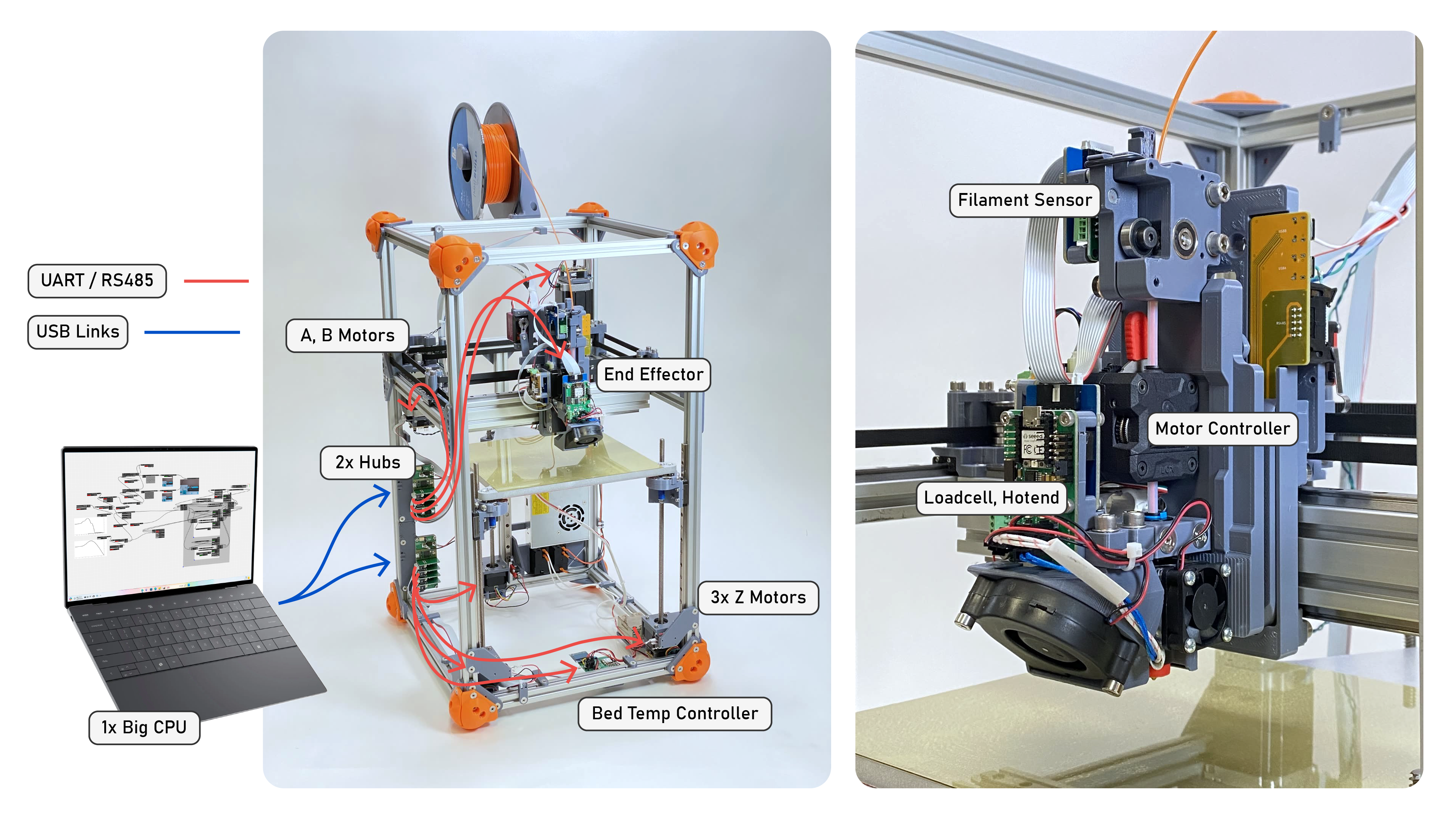
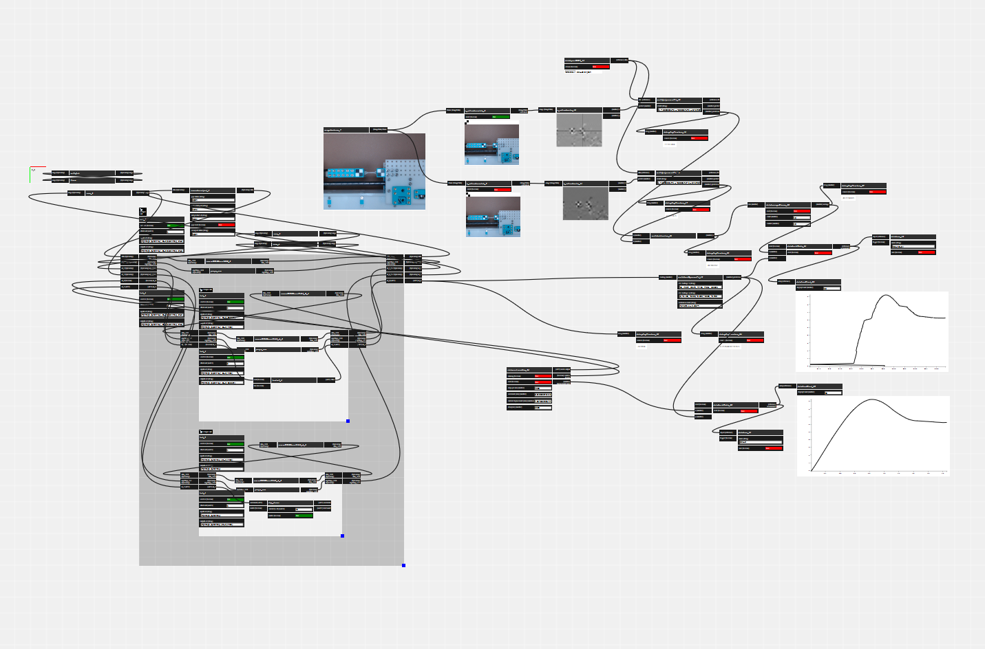
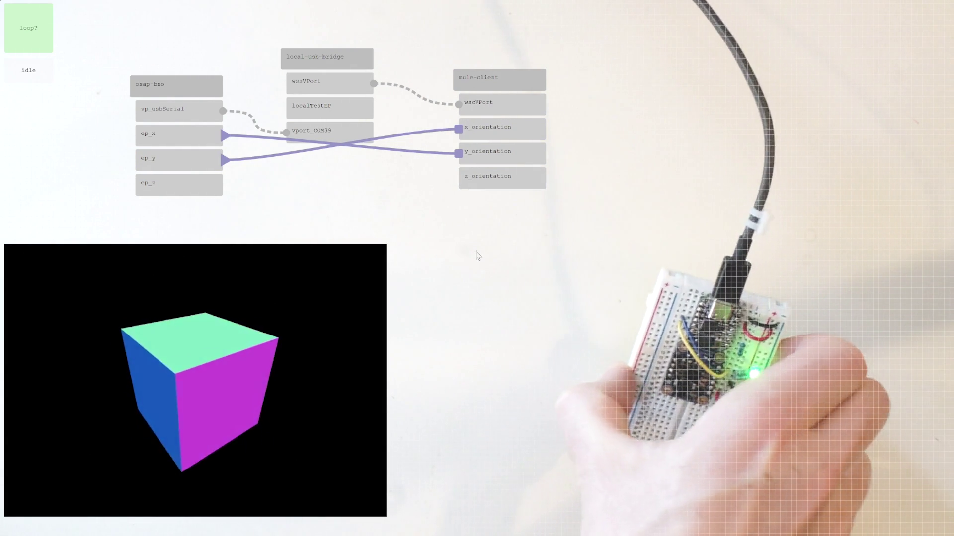
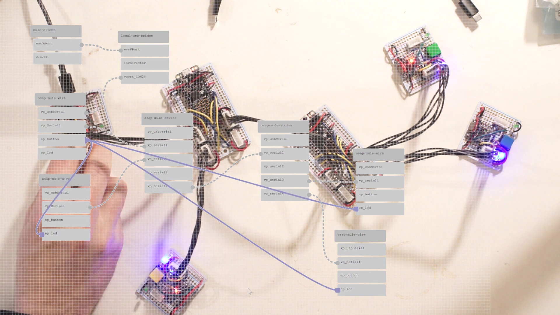
From Figure 1.8 and other discussion, it is clear that the systems deployed in this thesis are (1) always distributed and (2) sometimes messy. Structurally, they are all graphs, but I do not have a tool to visualize them as such. I would like to build a tool to do so.
A graph visualizer and editor would let systems developers quickly debug which hardware modules are connected, inspect their APIs, and build low-level data streams between devices. I have built a similar system in the past, but made the mistake of over burdening the graph representation: programs there had to be described entirely as graph entities. In an updated version, I would like to be able to interchangeably use scripting and graphs. I suspect that graph representations will be useful for low-level configurations, but that high level orchestration will take place using scripts.
(done) I plan also to include all of the graph editing API as script elements, meaning that a machine will be able to configure its own low-level systems; I anticipate that this may be useful for machines that need to alter their configurations during runtime, such as tool-changing systems.