1 Introduction
Machine building is a core competency for any industrial society because the technology that is available on the factory floor drastically changes how productive the economy is [1] and the quality (and quantity) of jobs that are available there [2], [3]. Perhaps more important is the manner in which workers interact with that technology — or if they can at all; some half a million manufacturing jobs were unfilled in the USA in 2025 [4] [5] and thirty thousand in Canada [6]1, largely due to a gap in the availability of skilled workers. These valuable jobs [7] often involve the operation and use of digital fabrication2 machines.
In this thesis I will present new methods and insights that improve our ability to build and operate automated machinery, but a prevalent anxiety with automation is that it will replace people with machinery, supplanting the labour share of value (which we all have access to) with capital expenditure (which is unevenly distributed). As David Noble relays in Forces of Production, the first CNC machines did so by replacing machinists’ tacit knowledge with computer programs that could be developed and managed in a top-down structure [8]. This centralized power and removed intelligence from the factory floor. Not only is this part of why there is a dearth of skilled work in today’s factories (operating as an automaton is much less rewarding than almost any other task), it contributes to our factories’ lagging productivity: the hype surrounding Industry 4.0 is driven by the notion that we can use technology to bring intelligence back to the factory floor, where it is most useful.
Doing so doesn’t have to be a zero-sum game: if we apply new tools in a way that we create new tasks for humans we can increase productivity overall without the dread, as Acemoglu and Restrepo report in [9]. Aspirationally our new manufacturing jobs should involve machine development and refinement as well as use. MIT studies have found that factory workers were hopeful about automation that allows them to do more complex tasks [10] and that flexible manufacturing (which involves rapid re-tooling of equipment) is of key importance if we want to bring manufacturing back to the west where automation has been poorly adopted [11] [12].
This motivates one of the central question in this thesis: how can we make the development and use of machines simpler? In particular, I am interested in replacing a pervasive and opaque representation for machine control (GCode, which lies between high- and low-level machine control tasks) with a flexible and interpretable systems architecture that can be modified and operated using commonplace programming design patterns. If we can do this successfully, we can make development cycles for new machine tools faster while also connecting them to more advanced algorithms. This in turn helps us to build new workflows for machine users that are based on real world feedback rather than iterative guess-and-check cycles. Those new algorithms can also provide feedback in a manner that more directly reflects the physics that machine operators develop tacit knowledge for.
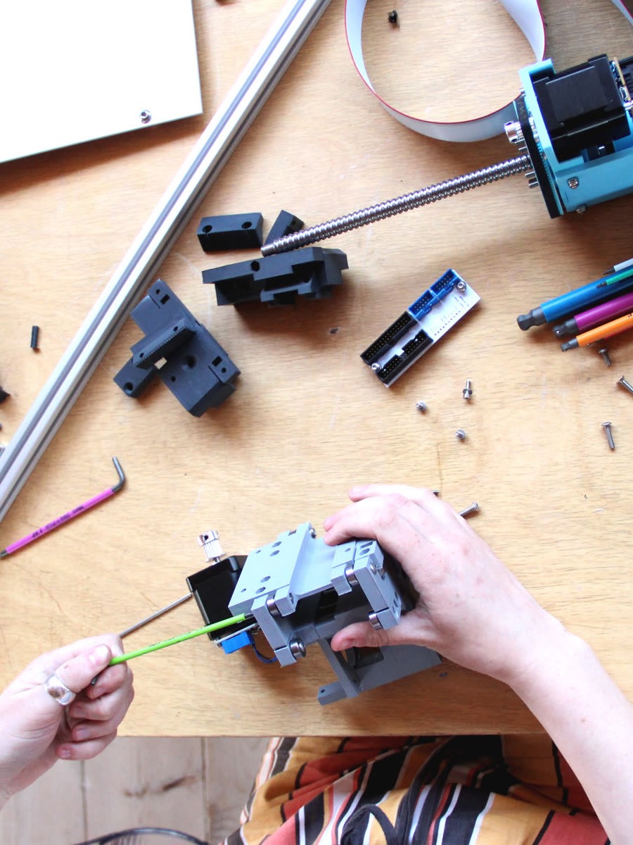
Machine building and use is also becoming increasingly democratized. For decades, manufacturers have used digital fabrication to build products in large and small volumes. More recently even small engineering firms are using machines to prototype designs in house, build automation equipment and tooling, and to perform process-specific tasks and tests. Alongside these engineers we find scientists, [13] [14], STEM educators [15] [16] [17], craftspeople [18], and autodidacts who all use (and develop) machines to learn: about our world, about mathematics and artistry, and about their ability to change the world while participating in our material economy. It is not surprising that engineers might develop and deploy machinery, but our scientists, educators etc. belong to groups whose main concern is not the machines themselves — these people’s heads are already filled with other (important!) knowledge. Understanding their tools should not require that they give up an exceptional amount of that valuable headroom.
Machine control is a task that I and many of my peers have found to be surprisingly nuanced; it runs us through a gauntlet of topics from power electronics and current control through time, space, and frequency domains and into model predictive control and nonlinear optimization. I have seen many people wade into these problems after having designed some hardware that they then want to control — assuming this must be a well solved problem — only to find the task riddled with “gotchas,” “traps for young players, 3” and frustratingly opaque tooling.
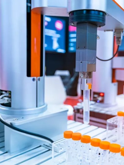
Besides my own friends and colleagues, I have been able to meet many small (and large) companies who are developing new machines e.g., for composite fiber layup, novel additive manufacturing processes, modular circuit assembly, valve calibration, medical device manufacturing, etc. Many of these firms reached out to our research group because they were in the process of rebuilding a controls stack internally, especially in cases where motion controllers were tightly coupled to process controllers.
Behind all of these technical activities are the real motivating questions that led us to developing that new hardware in the first place: why do these tools not feel like tools4, why can’t I easily modify an old machine to do a new thing, and why is it so hard to understand why my machine broke, or why the part failed, or why the output is less precise than I had hoped? These are all systems level questions that are difficult to answer if and when any of the system components are black boxed, 5 which is often the case with our machines.
If nothing else, I hope that this thesis can serve as a guide through these tasks, towards a world where building machines is more like building software; where we can find very good solutions to recurring problems available in the commons [21] and easily yoke them to our particular applications.
1.1 A Small GCode Primer
Understanding how GCode works, what niche it fills, why we might want to replace it (and why it is so pervasive) is important background for this thesis. To begin on that front, Listing 1.1 (matched to Figure 1.2) contains a basic GCode “program6” that cuts a square out of a piece of stock using a CNC milling machine (a subtractive tool, one-such machine features in Chapter 6).
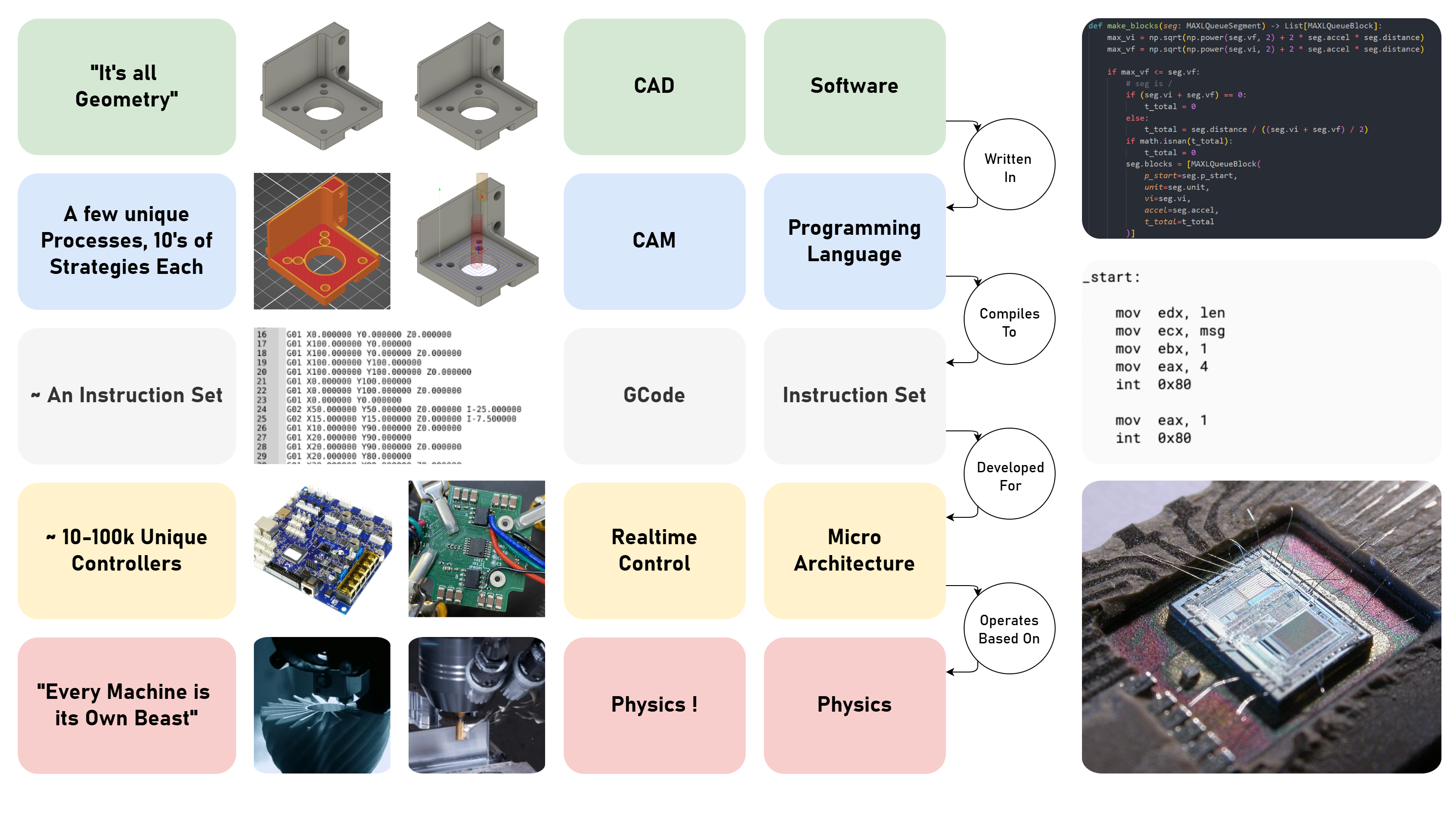
GCode was developed in the 1950s [22], [23] around the same time as programming languages, compilers, and instruction sets: in computer science we call these “layers of abstraction” and they help us to build complex things without worrying about the particulars. Programming languages allow software engineers to write algorithms without manually writing out machine instructions [24], and compilers rely on static Instruction Set Architectures (ISAs) to generate low-level codes without concern for how they are actually implemented in hardware (see Figure 1.4).
L01   G21                   ; use millimeters
L02   G28                   ; run the homing routine
L03   G92 X110 Y120 Z30     ; set current position to (110, 120, 30)
L04
L05   G0  X10 Y10 Z10 F6000 ; "rapid" in *units per minute*
L06
L07   M3  S5000             ; turn the spindle on, at 5000 RPM
L08
L09   G1  Z-3.5 F600        ; plunge from (10, 10, 10) to (10, 10, -3.5)
L10   G1  X20               ; draw a square, go to the right,
L11   G1  Y20               ; go backwards 10mm
L12   G1  X10               ; go to the left 10mm
L13   G1  Y10               ; go forwards 10mm
L14   G1  Z10               ; go up to Z10, exiting the material
L15
L16   M5                    ; stop the spindle
L17 G0 X110 Y120 Z30 ; return to the position after homing (at 6000) 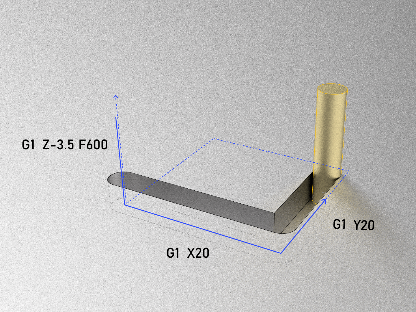
I compare abstractions made in software layering to those assumed by GCode in Figure 1.4. In computing, the approach works well: softwares describe programs at a high level, where we have lots of semantic meaning and complexity but relatively few “lines of code” for the actual description. Programming languages provide rules for software that ensures those descriptions are regularized well enough that they can be compiled into machine codes, which are written for whichever ISA that it will target. Machine codes are very low level: individual operations are very simple (add two numbers, move a value from one location in memory to another, etc.), but have little semantic meaning and there are very many of them; it is very difficult to make any sense of a program by reading the instructions emitted by a compiler. These in turn run well at the physical layer because computing hardware is extremely regularized: it has a clear interface for which instructions are possible and it works identically every time (barring e.g. a stray shot of radiation to the wrong memory cell). Computer science and engineering has gone a long way to ensure that this is the case. These abstractions are in place for reliability and consistency, and they also make code portable: high level programs can be compiled to run across many individual computer chips or even types of computer chips thanks to these regularizing steps.
GCode was meant to take a similar place in machines, allowing machine programmers (formerly machinists) to develop manufacturing routines that could be deployed on variable hardware [8]. This approach is stymied by two important caveats.
Firstly, while there are only a few ISAs for compilers to contend with (and even then, a real homogeneity around x86, ARM and now RISC-V7 in practice) there are perhaps tens of thousands of unique GCode interpreters8 and each has a unique “flavor” of GCode because each machine has different capabilities and configurations.
Secondly, physical processes themselves are also heterogeneous: even if we run the same job on a machine thousands of time, each is bound to be different: cutting tools wear out, feed stocks are of slightly different sizes and compositions, external factors like heat soak and ambient air temperature all change. Whereas computer science goes to great lengths to ensure the homogeneity of the lowest layers of its stack (the implementation of ISAs), it is simply not possible in manufacturing to do the same. All the while, GCode provides no recourse to access real-time information from the machine at runtime, i.e. it is entirely feed forward: if we want to describe an algorithm that controls a machine intelligently based on physical measurements, GCodes are simply not an option.
GCode also contains a mixture of simple instructions like G1 (goto position) alongside larger subprograms like G28, a homing routine that may involve coordination of many of the machine’s components. If we want to interrogate what G28 is actually going to do (i.e. to see which axis is going to move first), there is no way to inspect “one layer down” from the G28 that is blankly staring at us, unless we have access to the interpreter’s source code.
1.2 A (Very) Small CAM Primer
While GCodes can be written by hand, they are most often generated using CAM tools (for Computer Aided Manufacturing). When someone learns how to make things with digital fabrication, much of their effort is devoted to learning how to use CAM9. We often call this “machine programming.” CNC machine programming is notoriously difficult, whereas 3D printing CAM tools (known as slicers) are much easier to use (this is one of the main reasons that 3D printing has become so ubiquitous). Each has its own quirks, but follow a similar pattern: a 3D file is imported and positioned in a virtual work volume, and then various parameters are configured such that the software can generate a path plan (which will become GCode) for the selected machine. Figure 5.5 and Figure 6.4 give examples of printing and milling parameter sets respectively, and Figure 5.4 for a diagram of state-of-the-art 3D printing workflow. For a longer discussion of each, see Section 5.2.2 and Section 6.1.2.
For now the main issue to point out is that CAM tools are disconnected from the machines that they write instructions for. GCode does not encode any way to get data from the machine into CAM, nor are the parameters that users set in CAM related to physical models of the process.
1.3 Problems in State-of-the-Art Machine Control
1.3.1 Machines are Thoughtless
The simplest way that I have found to articulate the main issue here to say that digital fabrication equipment does not think about what it is doing, nor can it tell a user what it is capable of or anticipate errors that may arise from a particular program. When mismatches arise between CAM outputs and real constraints they simply fail. For all of its advance, most digital fabrication seems about as sophisticated as the inkjet printing we are all familiar with: sometimes straightforward and unsurprising, or else error-prone and frustrating, but never enlightening.
For example, a CNC milling machine itself has no ‘knowledge’ of the physics of metal cutting, chip formation (see Figure 6.1) or structural resonances even though these physics govern how we might whittle a block of aluminum down into the desired shape. In the same way, a 3D printer knows nothing of the rheology involved in heating, squeezing and carefully depositing layers of plastics in order to incrementally build 3D parts (see Figure 5.1). It is difficult to say whether any computer system has ‘knowledge’ of anything; in this case I mean that our machines do not use any information about the material physics that they are working with while they operate (most also have scant knowledge of their own physics). Where state-of-the-art machines do use sensing and feedback it is normally relegated to one subsystem: for example most industrial milling machines have encoders for positional feedback on each axis, and some high-precision mills also measure temperature along each axis — but these are used in the subsystem that positions that respective axis, feedback doesn’t make its way back to higher order controllers, nor to our CAM tools (or to us). In this thesis, I try to close a longer loop across the machines’ global control controller, using matched computational models of the whole system (process and motion).
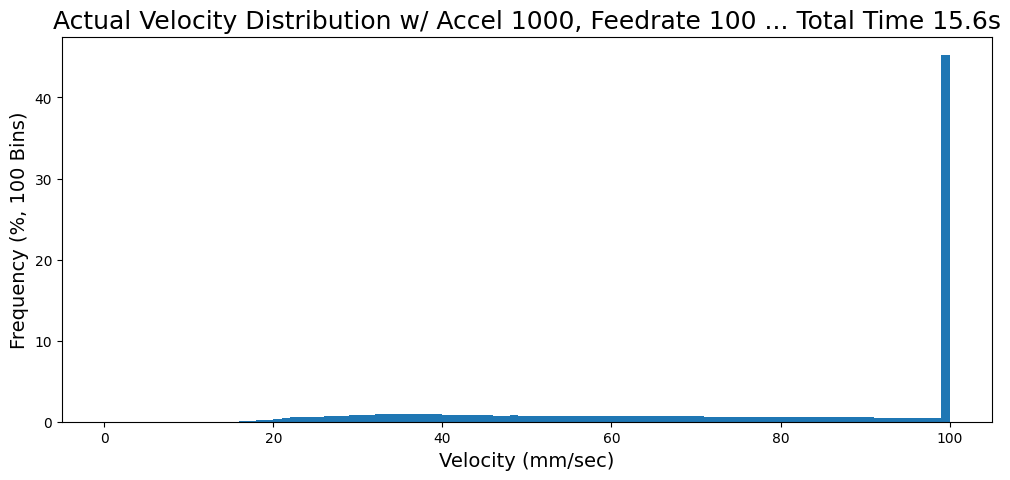
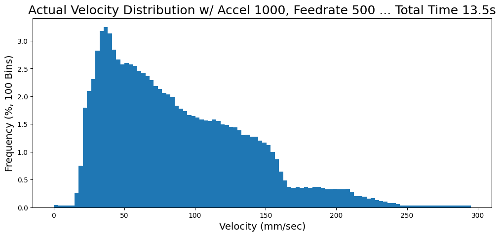
This means that in order to operate successfully, an understanding of these physics (constraints!) must be embedded within GCodes, but those are developed by hand in CAM tools where we tune low level parameters that are directly correlated to instructions, not physics. For a quick example (see Section 5.11.2 for a much longer discussion), we tune directly the speed that our machines should travel at during operation. Speed is physically constrained by the machine’s actuators, mass, and frictions — and changing it also changes process parameters, like how much cut force will be generated. When we’re looking at these values in a CAM tool, nothing there can show us how close to those limits we might get if we try to increase the speed. A similar story is true for machine builders (especially non-professionals like those scientists and educators I mentioned earlier), because many state-of-the-art machine controllers are configured using low level / feed-forward parameters.
This poses a problem for machine builders (who need to carefully tune their motion systems by hand) and machine users (who need to intuitively tune a slew of CAM parameters). It also means that many machines may not operate near their real world optimal limits because hand tuned parameters tend to have considerable safety margins. Finally, it prevents us from learning from our machines: where the limits are, where we are operating with respect to those limits, and how we might best change our machines or our approaches in order to do better.
1.3.2 Machines are Poorly Represented
The root of those problems is that machine controllers and users don’t have good representations of machines — to model what they are, how they are configured, what they can do, and what they are doing. A slightly more precise way to say this is that many state-of-the-art machine representations are lossy — they are often misaligned with reality, they fail to capture important phenomenology, and are difficult to correct.
For example, in line 10 of Listing 1.1, we tell the machine to do "G1 X20" — move the X axis 20mm to the right (from its previous position established in line 5). It is impossible to know from the code alone which motor (or combination of motors) is actually going to execute this move; there is a system configuration that is hidden from us that is unique to the individual machine. This seems like a simple problem (simply write down the configurations, right?) but is a major hurdle for companies like AutoDesk, whose CAM software (Computer Aided Manufacturing, see Section 1.2) must interface to many machines, and needs to know exactly how e.g. the X axis moves relative to the rest of the machine in order to simulate collisions and show the user what their program will do, and so that their software can write the correct GCodes. This is even more difficult with advanced machines like mill/turn machines10 where many users result to writing GCodes directly — a clear failure of what is meant to be a low-level layer; in software, writing machine instructions directly is incredibly rare.
In the state-of-the-art, this configuration is set up in the machine’s firmware11, which is difficult to inspect and edit. These “hidden states” cause all manner of headaches for educators, hobbyists, and scientists who want to re-purpose off-the-shelf controllers for their own inventions, especially if their machines deploy nonlinear or novel kinematics12. One common result of this problem is that we find machines in the wild whose controllers are convinced that they are a 3D printer when in reality they are e.g. a gel extruder [25] or a liquid handling robot [26], or cases where authors have had to develop their own ad hoc control systems (rather than re-using available designs) [27] [28].
What a machine builder normally wants is a computational model of their machine that is aligned with reality — this is half semantic alignment (any axis can be named “X” if we declare it to be, but our CAM and controller should agree on the declaration) and half tuning and model fitting (how are the kinematics arranged, how much torque is available, and what happens if we apply some amount of it over the course of one second?). With a complete computational models of our machines, we would be able to simulate and visualize them in software to learn what they might do given certain instructions. The danger in this approach is that the simulations could easily be misaligned with reality, which is why I focus on using in situ instrumentation to build the models used to represent machines: i.e. we use the machine to build models of itself.
We also want models for the process physics that our machines control. In Figure 1.8 I show how different aspects of machine physics, each of which operates at varying time scales in varying aspects of the controllers, all relate to overall machine operation. As I discussed, GCodes nor CAM tools represent these physics directly. In Section 1.5, I discuss how we might use models to represent this aspect of machine control as well, and how doing so allows us to frame machine operation as a constrained optimization task (which it already is, just implicitly) more directly.
1.4 Systems Integration and the Partitioning Problem
OK, problems aside, we can start working our way towards solutions and answers. In this thesis I take primary interest in how systems integration (SI) relates to machine control and machine operation. Good systems integration often involves breaking a big problem up in to lots of little problems, but where should we delineate those boundaries, and how do we ensure that we don’t reduce system performance or capability when we do so? I call this the partitioning problem, simply put:
Given a system with certain requirements, how should it be decomposed into components (modules) and how should they relate to one another (interfaces)?
Systems integration [29] is widely recognized as a critical and difficult part of the engineering process. In my time building and using machines I also found that really difficult problems emerge most often during this step: when we start putting things together, new behaviours emerge that weren’t apparent from component behaviour alone. Besides my own personal experience14 (and observations of students’ troubles while teaching [30] [31]) there are a few famous SI bugs from massive engineering projects to recount; the Mars Climate Orbiter failed due to a divergence between a software interface specification and the actual implementation [32], the first flight of the Ariane 5 rocket failed due to an integer overflow15 error that arose because developers re-integrated old firmware in the new system [33], and the Airbus A380 was delayed for years thanks to a difference in the software version that two collaborating teams used, leading to wiring harness length mismatches [34].
In studying machine control, I found a pervasive gap between research on low level machine physics (that govern their operation) and high levels of control (that must manage those physics), which I explore in the background sections for 3D printing (5.2) and CNC machining (6.1.4). In many instances, researchers in these fields are hampered by limits to SI presented by GCode: they cannot readily apply their new methods or models to existing hardware and instead need to “work around” GCode interpreters, in some cases going to great length to model the behaviour of those controllers separately because they cannot access their internals directly.
Conversely, when we can tackle big SI problems we stand to gain many new insights on these processes — a selection of which I will relay in this thesis. These are valuable not only to machine researchers but to users, developers, and to society writ large since improvements to these systems have fairly direct relation to our collective ability to produce real and valuable new things.
1.4.1 The Economic Partitioning Problem
This is a thesis on machines, not economics, but state-of-the-art systems are often partitioned along economic boundaries (which firms build which parts of a system), not just technological boundaries (which aspects would most optimally go where for performance and legibility). This is especially true in larger, older, and broader reaching industries like manufacturing. At the same time, technological innovation can change economic partitions, so it is worth covering some background here so that we can understand this aspect of GCode’s pervasiveness and position, and also to motivate our research efforts.
At economic scales SI relates to how individual firms develop and manage the many components, suppliers, and networks that enable their activities [35], [36]. There is an excellent historical example of good economic scale systems integration that occurred during the emergence of the Silicon Valley that we know today that is recounted in Design Rules Vol. 1; [37] the outcome of which is a world of computing hardware that interoperates across firm boundaries, even amongst competitors. We build PCs and servers with RAM built by Micron, SSDs from Samsung, processors from Intel and AMD, and these all work with keyboards, displays, etc. from a litany of other manufacturers. Engineers in these firms do not coordinate interoperation with one another directly, they rely on standards and shared practice. There is a parallel story in the development of the software that runs on this hardware, where an open ecosystem of interoperable modules built using portable languages and compilers now powers most of the programs that the world uses day-to-day [38] [39] even though prominent computer scientists though this was impossible as recently as in 2004 [40] 16. Economic researchers call this a form of collective intelligence [41] or collective invention [42]. Together these represent a world of tooling for the development of information technology that has by many measures powered the world’s economy over the last three decades, culminating in the emergence of much-lauded “AIs.”17
On the other hand tooling for machine builders is notoriously proprietary — even large firms like Fanuc, Haas or Robodrill contract the controls for their machine to other firms like Siemens and Heidenhain, whose algorithms are kept close to the chest [43]. This is despite the fact that all the world’s digital fabrication tools rely (especially at lower levels) on the same core set of algorithms and control methods for operation: motion control being top amongst them. If state-of-the-art design patterns for these core competencies were more broadly understood and easier to implement and extend, we may see a similar level of growth in the “real” part of the economy as we did recently in the infotech and finance part, i.e. the sectors that provide us with physical, manufactured goods and their byproducts: housing, healthcare, and food.
I could go on at length on this topic, but I will stick to the point: advances in technical solutions to the partitioning problem have major ramifications for economic partitionings [44], and efficient partitioning leads to better outcomes across layers of the economy: almost nobody looses. This is well studied, in particular in [37] and the field of Transaction Cost Economics [45]. Collaboration on new interfaces for these partitions is also often easier than we think, as Elinor Ostrom showed us [46], [47].
Conway’s How do Committees Invent [48] shows that organizational partitions imprint in their technical products18 (for better or for worse). GCode’s persistence is perhaps most of all a result of this effect: developers of machines rely on it as a stable interface between their hardware and controllers and CAM companies’ toolpaths. The schism between these two halves of the machining process (programming and operation) emerged during the development of GCode, as I discussed in Section 1.1. Once these interfaces have emerged, we also have industrial inertia [51] to contend with; existing interfaces lead to the emergence of firms on either side of the interfaces (CAM companies, control companies), who then develop new technical products that, given those firms’ market position, do not easily span those interfaces19.
This thesis will not contend directly with these economic effects, instead I hope to show the value of integrated digital fabrication systems to encourage more efforts in this regard. I will try to point to what we can learn and what is possible if we can more flexibly solve the partitioning problem.
For a concrete example of how improved partitioning can push changes up into economic structures, [52] is an excellent study that recounts how the NetScape browser was intentionally re-engineered with modularity in mind in order to launch it as an open source project. That effort was a success: it is now called Firefox.
In 1999, Internet Explorer held 99% of the browser market share, which was an alarming trend for proponents of free speech and democratic access to information [53]. The Firefox rewrite occurred between 2002 and 2004, and its market share peaked at around \(30 \%\) in 2009. It is credited as one of the main reasons that Microsoft’s monopoly was unseated [54] and its success enabled the establishment of the Mozilla Foundation, a key maintainer of and advocate for “openness, innovation and participation on the Internet.”
1.4.2 The Technical Partitioning Problem
So, what are the technical constraints that drive various approaches to the partitioning problem? There are a huge number in total; we should focus the scope back down towards the relevant topics in this thesis — machine control systems: the software and firmware20 that make machines move (and in this case, collect data from them), and the electronic hardware, motors and sensors to which those are attached. Machine controllers are just one component of machine workflows: the sets of operations that we carry out as we use machines. So, in this framing GCode is the interface that partitions smart / high-level steps in machine control workflows (CAM) from low level steps (control).
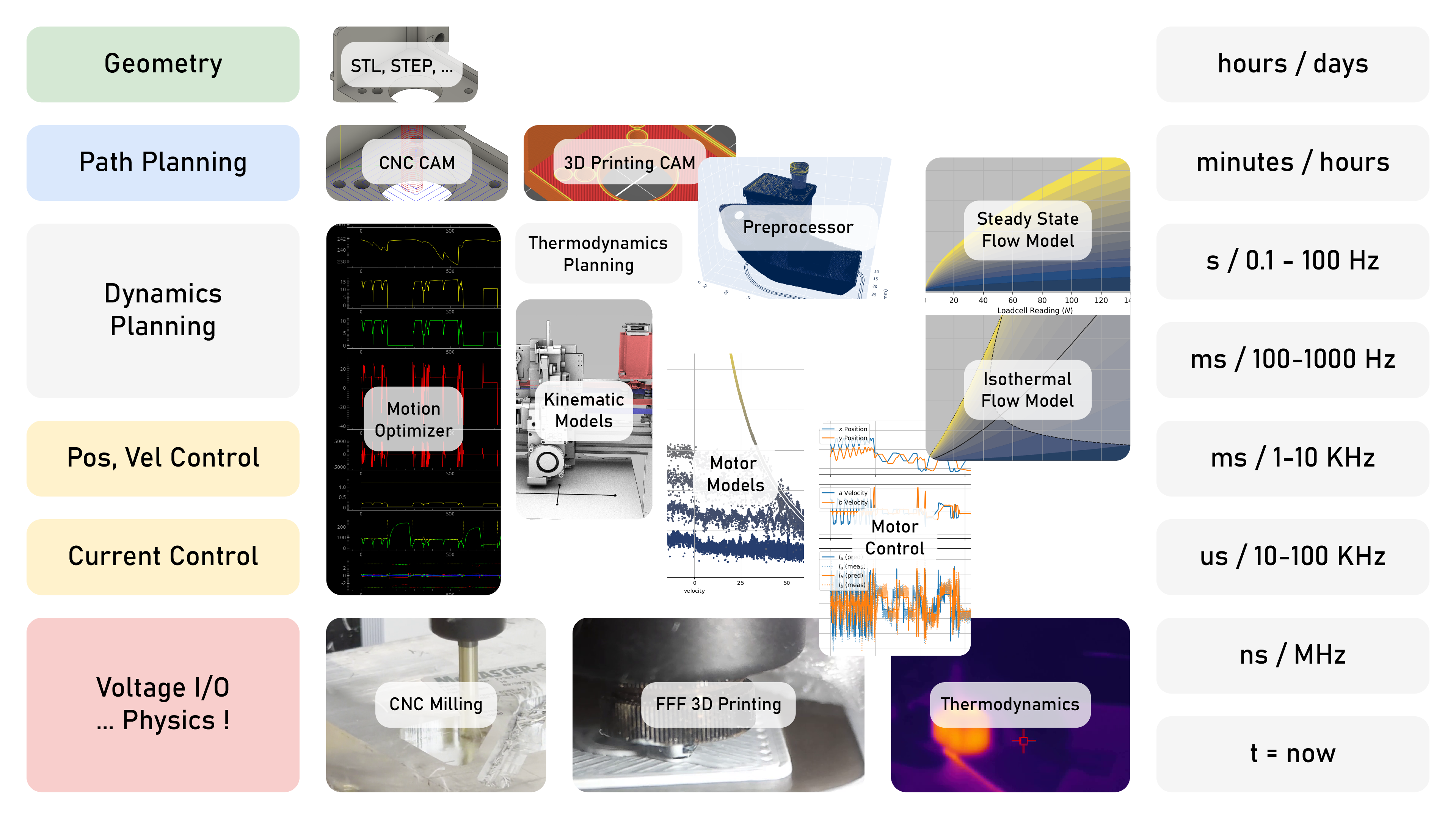
In Figure 1.8, I expand on the layering from Figure 1.4, organizing control tasks in terms of the time scales that are relevant for each. At the coarsest level we can bin these into two groups. High level tasks like design can happen slowly (years, even!), and path planning (generating toolpath geometries, i.e. CAM) can take hours or minutes. Low level tasks need to happen in realtime alongside machine operation, this includes dynamics planning (selecting exact control values for those paths) which typically happens at relatively low rates (hundreds to tens of milliseconds), and direct control of hardware needs to happen quite quickly (on the order of hundreds to tens of microseconds).
So, time is one partitioning axis. Tasks along this axis tend to correlate with the time constants21 of the physics that they control: motor current control needs to happen in microseconds because voltage (which we apply to motor coils) very quickly turns into current, position, and velocity control in milliseconds because that is about as long as it takes for torque to change velocity, etc. The dynamics planning step can be slower than other realtime tasks. For example the top level human motor control loop is only about 10Hz [55], humanoid robots’ top level loop can be anywhere between 50 and 250Hz, and e.g. the MIT Cheetah’s is 30Hz [56].
Better planners can be slower because they are able to anticipate system dynamics farther into the future, but they also require more compute power — another axis in the partitioning problem. Luckily fast tasks are simple and complex tasks are slow. In reality this hierarchical setup has emerged in practice because of the partitioning problem: if we could simply run all of our controllers on one CPU and eschew the organizational complexity we would.
Along a compute partitioning axis, we also have the straightforward requirement that low level tasks need to run in firmware (where compute power is limited) because they interact directly with hardware. Path and dynamics planners don’t have this requirement, but they do need to communicate with layers that do or be directly integrated with those layers, e.g. running motor control and dynamics planning steps on the same device. Direct integration of these layers is common in simpler, more accessible machines like those used by educators, hobbyists, and open source scientists. See Figure 3.1 and Section 2.2.4.1 for examples of those and Section 2.2.4.2 for examples of systems partitioned such that the dynamics planner communicates with motors and sensors over networks.
It is implicit so far that each of these control aspects must be connected to one another somehow — but how well we can do this is really what drives us to choose some partitions over others. It is difficult to simply run all of our controllers on one CPU and then (for example) transmit only the very lowest level, simplest control states directly to our hardware because of bandwidth limits between devices. We can try this as in [57] (and it can actually work very well22 for simple systems), but doing so imposes performance limits that are directly related to those bandwidths.
Dynamics planners in particular sit in an interesting middle ground. They require much more compute than other tasks in the “low level” bin, but they don’t require direct interaction with hardware (i.e., they can run on computing systems that are not exactly embedded). They are also very central to machine operation — they’re our bridge between high and low level tasks. That means that the amount and quality of the bandwidth into and out of this layer is critical. Communication between path planners and dynamics planners is important because we want our machines to quickly respond to changes in the plan. In this thesis bandwidth from all lower layer of control into higher layers is key because we are trying to model machines using the data that they generate. Data from the dynamics planner itself is especially valuable because it is where global system states are predicted. Communication from the dynamics planner into lower layers needs to be fast and also deterministic23 because if the planner fails to transmit new instructions to a machine’s actuators they will make errors or enter unsafe states. Determinism is the last constraint that I will mention here, and I will also note that it is not a common property in large compute systems because their operating systems can arbitrarily interrupt programs that we deploy there. The same is true of high level languages, which have garbage collectors that can also interrupt operation. For this reason, state-of-the-art dynamics planners tend to run on unique compute hardware that sits on the boundary, normally small Linux-based computers that run specialized “realtime-patched” operating systems.24
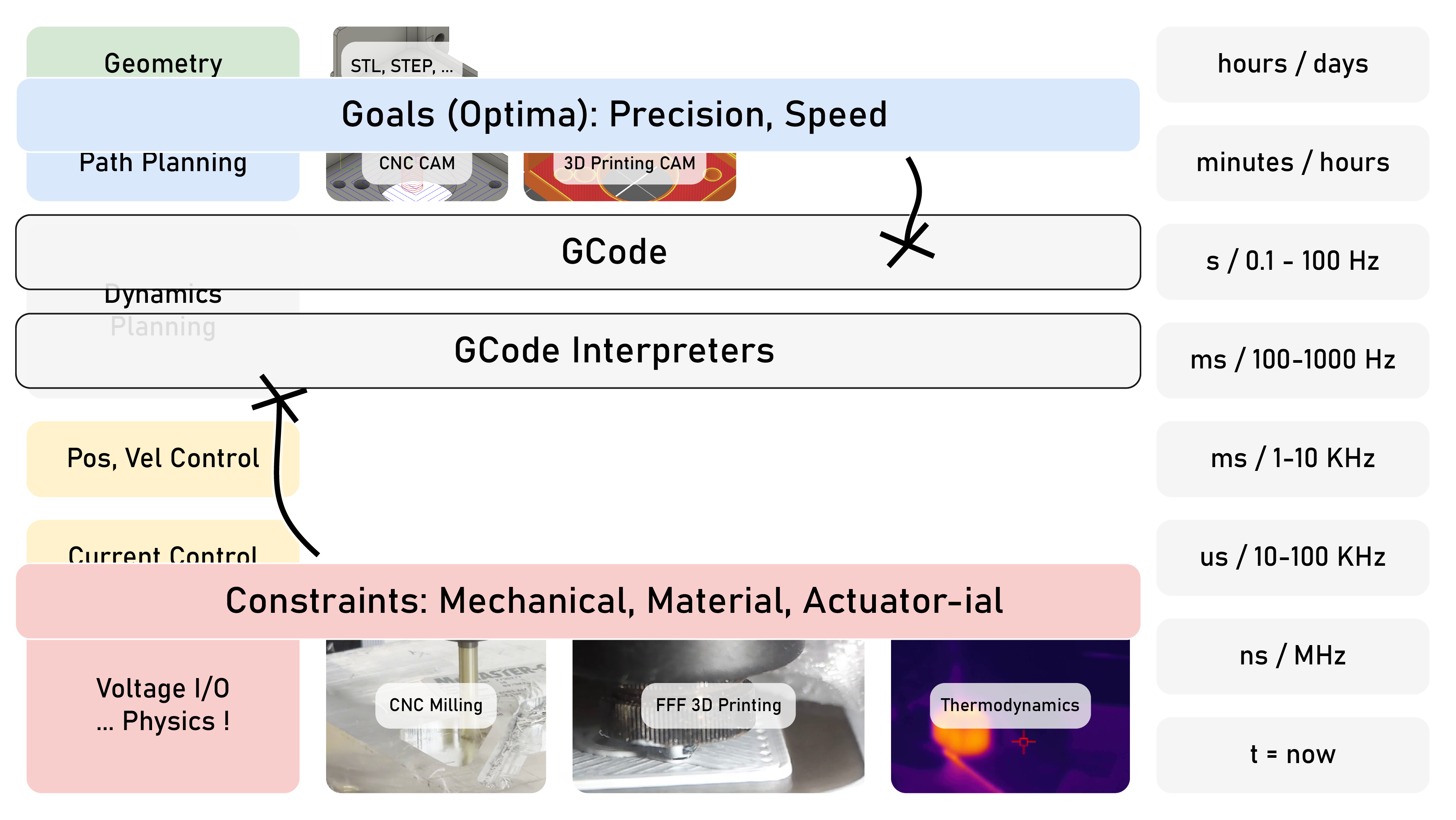
By now you probably have a sense of why GCode lies where it does; it is exactly where we would expect a sensible partition should be such that we cleanly split big (but slow) computers from small (but fast) embedded25 hardware. Unfortunately it is a one-way interface with limited descriptive ability; I discussed how this lobotomizes machine controllers in Section 1.3.1, how it makes it more difficult to understand and edit machine systems in 1.3.2, and how it prevents us from understanding how the parameters we set in CAM tools affect real machine physics in 1.3.3.
In this thesis I expand on a long line of systems architecture work from my own research group and elsewhere to develop some new solutions to the partitioning problem.
For more flexible partitioning of modular machine systems using networked control across big and little compute I developed OSAP (2.3). PIPES (2.4) introduces a design pattern for systems representation that combines dataflow with scripting; this lets us configure and task26 partitioned machine systems in a unified representation. I extend that to develop motion planners explicitly as dataflow programs (2.5), using a synchronization pattern that helps us to more successfully relocate the dynamics planning step from embedded devices into larger computers, where we can take advantage of more flexible and powerful computing tools to extend their performance and make them smarter; I call this exercise crossing the realtime gap. I also build a set of modular circuits that show how the partitioning problem extends into the design of hardware (Chapter 3).
By developing new systems architecture for machine control, I want to show concretely that the technical reasons that drove historical partitionings are gone or disappearing. There have been many advances in i.e. embedded computing, parallel computing, software design patterns, and automatic differentiation and just-in-time compiling (almost) any program27 between the 1960s (when GCode was invented) and today. These allow us to build machines that are flexible, intelligent, etc.
That this is possible is not a new insight, but efforts to actually do so have been limited; I get more specific about how the systems in this thesis differs from the state-of-the-art in Section 1.6.2. In 1.6.3 and 1.6.4 I describe contributions in control and modelling that would have been challenging to make without having done this organizational work first. On the other hand, some aspects of the systems that I developed hampered my efforts — I discuss those in Section 2.8 (where I also recount the successes).
1.5 Machine Operation is a Constrained Optimization Problem
Improvements to low level partitioning of our systems helps us to make better sense of them as a whole. Just a few moments ago I said that machine control is really a constrained optimization problem. But what does that really mean? Ignoring what we have discussed so far about how all of these machine systems are assembled, at a higher level we have optimal outcomes that are easy to name (making our parts: precisely, quickly), and constraints (which emerge from machine and material physics: we cannot cut with infinite force or move at unlimited speeds). If we can articulate constraints and optima computationally, we can solve the problems numerically, and if we can articulate them more directly to the human beings who design and use machines, we could help them to better understand the problem they are solving and make better decisions as they do so.
In the state-of-the-art, many of these constrains are implicit and require that we carefully author our GCodes such that they are not violated, meaning that the use and design of machines requires a lot of tacit knowledge and intuition that can take years to develop and is difficult to teach to others besides through apprenticeships and direct experience. Most machine controllers are also configured using parameters, not models, and so machine builders also have to guess-and-check for good motion control parameters or must develop their own models and model fitting routines for their machine’s dynamics and translate those into controller configurations. That is hard to do using GCode based controllers.
So, the second major theme in this thesis revolves around this question: can we frame this constrained optimization problem more explicitly? And beyond that, can we use the models that we develop to describe machines as an interface between otherwise partitioned layers of control?
This comes in to play at first very directly (in dynamics planning) but also in a larger outer loop about how we organize workflows. Again, it is fairly well known that optimization based controllers can be more performant than their heuristics based counterparts, but there are limited examples of their application to machine tools, especially in 3D printing.
Consider again Figure 1.9: optima are described at the highest layer here, whereas constraints emerge from machine physics, all the way at the bottom. This means we need to learn which model formulations are appropriate for the task, which subsystems should be modelled together and which separately,28 and how to build those models: can we use the hardware that they describe to build them directly, eschewing larger cycles through offline metrology equipment? Can we use the same models throughout, for heavy planning tasks and for fast control tasks, or will we need to lobotomize some of them? What does a dynamics planner look like when it optimizes over motion and process constraints together — how much performance would that unlock, and does it have any fundamentally new capabilities? Which models or constraints turn out to be most important: actuators, stiffnesses, processes?
And how about at the workflow level: can we use models to reduce or eliminate guess-and-check parameter tuning from state-of-the-art CAM? What about in cases where we still need heuristics, can we reframe those heuristics so that they more relate more to machine physics? If we are successful and our models accurately represent machine physics, what new things can we learn about machines as integrated systems that we couldn’t learn from their components alone?
1.6 Key Questions and Contributions
The broad goal of this thesis is to take these scattered and sometimes misaligned machine systems for control and configuration and try to re-organize them into comprehensive, comprehendible and computational representations (models and programs). Doing so will let us operate our machines more effectively, reduce the parameter space that requires trial-and-error tuning, help us to rapidly build new machines and teach us about those that already exist, and enable us to connect them to smarter control algorithms.
Machine control is an old field that represents many years of collective effort, and I am proposing to replace some of its core assumptions. This is possible now largely due to the ever-increasing ubiquity of computing: the processing power we can now buy for less than one dollar and integrate into a motor driver outstrips (by a few orders of magnitude) what was available at an institutional level when GCode was first developed. This new availability, alongside years of my colleagues’ work, leads to the handful of new contributions that I have been able to make.
Many of the components or key ideas in this thesis already exist piecewise in the state-of-the-art, but they are seldom integrated into digital fabrication technology. For example there are excellent reconfigurable systems design patterns for large distributed systems like the web, but they have not been mapped into the embedded devices that we use to operate machines. There are also excellent model-based control strategies from the world of robotics, but they are less often applied in digital fabrication, and where they are their deployments are limited to smaller subsections of the control problem, for example building predictive models but not controllers that can use them or building predictive controllers for just process control or just motion control, not connecting those as a unified optimization problem. This too is largely due to GCode’s persistence: it prevents researchers from taking their contribution in one of these subdomains and applying it in an end-to-end manner. The overarching goal here is to help us imagine what is possible if we can manage this systems integration task, to connect machines, their models, and their users (and designers!) together across all of their emergent behaviors.
In this section, I will summarize the set of questions that this thesis asks29 and which answers it provides, pointing out to relevant background sections to compare what I learned here to what we already knew.
1.6.1 Guiding Questions
A set of guiding questions runs through this thesis. The first asks what kind of systems architecture would enable us to develop feedback-based machine control workflows. What programming representation lets us easily use the same hardware for model building and model-based control? And rather than re-building controllers for each new machine and process, can we do this in a way that is modular and reusable across the heterogeneity of machine processes? How can machine controllers be described when they consist of both high- and low-level components, i.e. how do we cross the realtime gap without moving between formats or programming models? Machine control also requires that software is matched to hardware, alignment that is normally done with manual configuration which can introduce errors. How can we apply design patterns from larger distributed systems to automatically build high-level programming schemas that match hardware, and then detect errors when programs are misaligned with the hardware they should be controlling?
The second is a question of representation: what types of models do we need in order to capture and represent machine physics — for their motors, for their kinematics, and for their processes — and can we build those models using the machines themselves?
The third re-frames machine control itself. If machine control is fundamentally a constrained optimization task, and that optimization is performed intuitively in the state-of-the-art by machine operators, can we instead re-frame it as an explicit, numerically solved constrained optimization problem? Are the solutions that emerge faster or otherwise better than the state-of-the-art, or are the gains only marginal? Among the many tools and formulations available for constrained optimization, which set should we apply?
The fourth is a check on the previous. Models are sure to miss some aspects of machine control that remain easily understood intuitively, and model-based control risks turning well-understood and productive processes into black-boxes; this would prohibit machine operators who already have a strong understanding of their hardware and processes from applying that knowledge, and make it more difficult for newcomers to learn. How then do we combine models with heuristics where they are still valuable, and can we present model and optimizer outputs in a manner that is informative for machine users and designers?
The fifth asks what a complete feedback-based digital fabrication workflow might look like, and how it performs against the state-of-the-art — in particular, how do we reflect heuristics-based tuning more directly against the underlying physical constraints?
Finally, I ask a similar question to the one above but framed around machine design as a practice: how can models and optimizers help designers to evaluate their machines, and how can models be used as tools in the machine design process?
1.6.2 Contributions in Mechatronic Systems Architecture
To answer the first question above, I develop a few core methods for the thesis, some of which are novel in surprising ways.
In Section 2.3 I build OSAP (for the Open Systems Assembly Protocol), a networking architecture that connects workstation-scale computing to low-level firmwares using mixtures of heterogeneous links, and builds in each context a consistent runtime where task scheduling is aligned with network scheduling. This resolves heterogeneous modular systems as a kind of distributed operating system in which we can build distributed machine programs. The networking scheme is based on source routing, a pattern most often used in spaceborne networks for its extreme reliability and robustness. Source routing is much simpler than the IP-based networks used in most other distributed controls architectures, whose main components require operating-systems-scale computing to operate. This enables us to include embedded devices as first-class members of our systems rather than building custom bridges that integrate them piecewise and limit the development of direct embedded-to-embedded dataflows. In fact, each device in an OSAP network is itself an internetworking device, not just an endpoint. OSAP’s internal runtime is expressed as a small local network whose operation is defined by a bytecode that extends across the network. Those bytecodes can instruct the runtime to move data between local ports, or between ports in multiple runtimes by inserting extra source-routing instructions. Source-routed networks are simple to operate but require that transmitters understand their local network topology because routes must be written into packets at the source. Normally this is done by hand using pre-defined network configurations, which limits rapid reconfiguration. In OSAP I combine low-level network operation via source routing with high-level set up via discovery and remote configuration; the first step toward this is OSAP’s network discovery service, which uses graph traversal over source routes to recover network topologies from the systems programmer’s point of view. By simplifying existing synchronization patterns, OSAP also provides a clock synchronization service, which is the basis for coordinated control and sensing for the machines in this thesis.
Sections 2.4 and 2.5 cover my progress on programming models for modular machine control. In Section 2.4 I develop PIPES, a programming interface that represents distributed systems using dataflow and remote procedure call semantics. This allows us to develop machine algorithms whose components are made up of firmware and software modules together, and to both configure and task systems in the same script — i.e. get them up and running without considering multiple hidden layers of configuration. PIPES extends OSAP’s discovery layer to add a systems discovery layer that builds a Systems Object Model (SOM) spanning network and program configurations. It can automatically build programmer-facing interfaces and reconcile real-world configurations against program-defined configurations at runtime, preventing errors that emerge if systems are subsequently modified. It does so using remote hardware and software modules’ own internal descriptions of their capabilities; we go directly from remote source code, to shareable data schemes, to programming interfaces. PIPES can also configure dataflows between devices, because those flows are specified at a network layer on top of OSAP’s source-routing scheme and combined with a dataflow model. Other distributed systems use more complex data-based routing schemes that are overlaid on sophisticated IP-based networks and run on operating-systems-scale computing. OSAP and PIPES instead use simple networks and simple rules for data transmission and program configuration, neither of which are mediated by stateful internal systems: we remove these internal states by coordinating configuration at a high layer that uses the SOM as an interface to write lower-level instructions against. While this is simpler than other distributed systems, it is more complex than statically-configured controllers, so to span these two domains (which are commonly combined using the bridges I mentioned earlier) without changing representations, we need to develop a series of small Model-View Controllers (a software architecture from the web) and combine their outputs to generate the SOM.
Within the PIPES framework I develop MAXL (Section 2.5), a motion control framework for distributed but coordinated execution of machine controls. MAXL is uniquely suited to be deployed within PIPES, and is architected to be useful in cases where we need to cross the gap between high-level computing and embedded computing — framing distributed trajectory generation and interpolation on a time-encoded basis, and introducing a configurable gap of time between these two ends of the problem. It uses a fixed-interval time encoding that makes network loading between these layers more deterministic when compared to spatially-defined trajectory representations, which (for example) require more bandwidth in areas of high geometric detail than they do along linear segments.
In Section 2.6 I make a complete comparison of the systems developed here against the state-of-the-art, and in Section 2.7 I summarize how those architectural deltas uniquely enabled the other work in this thesis. I show how they transform GCodes to just “codes” (programs), how they enable reconfiguration of hardware for new software, and reconfiguration of software for new hardware. I also show how they help to build machine models by revealing internal control states, aligning those to sensor readings, and allowing us to deploy powerful but indeterministic computing for model-based control. In Section 6.3.1 I show how even simple motion controllers, once exposed as software objects that can be used virtually, can provide valuable feedback and insight to machine users for CNC machining — especially when coupled with machine models, where we can then generate process measurements that would be unavailable otherwise (Section 6.3.2). Finally, all of these experiments run on a modular kit of control boards that I develop in Chapter 3.
1.6.3 Contributions in Machine Control
With these new systems integration tools, I can begin to answer some of the questions about model-based control of machines.
In Chapter 4 I develop a velocity planner that expresses machine control as an explicit constrained optimization problem, and show that model-based control can exceed the performance of heuristics-based solvers that are common in the state-of-the-art for the same task. This requires that I develop a few additional methods: a closed-loop stepper motor controller that can learn some of its own model parameters (Section 4.3.1), models of machine mass, damping, and kinematics (Section 4.3.2), and the planner itself in Section 4.6.
A core goal of model-based control is to use models directly as constraints in constrained optimization planners. Even in state-of-the-art machine systems and in other research, motion controllers still use proxies for these constraints; they describe maximal jerk, acceleration, and velocity values to limit machine motion. The planner that I develop leverages high-power computing hardware (the GPU) and modern optimization frameworks (developed for Machine Learning) to articulate the problem directly against physical models. OSAP and PIPES make connecting this compute hardware to our machine hardware more straightforward, and I also carefully formulate the planner such that its program can be parallelized for the GPU. The framework that I use is written in Python, which is also a preferred language for model building. This means that we can use the exact same computational representations in machine modelling and in machine control, and update them without recompiling planner firmwares, which connects machine modelling to machine control more literally than was possible before.
To examine explicit optimization across not just motion but process control, I develop in Chapter 5 a 3D printer that models polymer melt flows (Section 5.5), and extend the planner to include these physics in Section 5.9. This demonstrates a few things. The velocity planner from Chapter 4 is flexible enough to describe not just motion control but also process control. These tasks are of course coupled in the real world, but state-of-the-art systems control each aspect separately, with process control implicitly configured by parameters in CAM tools and motion control via velocity planners that run in lower-level interpreters. Process models for 3D printing of thermopolymers can be developed using the same hardware that controls them, eschewing an outer loop through process metrology on standalone and expensive hardware. To do this I develop new models for the process that extend the state-of-the-art in two ways. First, they are modelled across a range of nozzle temperatures to capture a broader set of possible process parameters. Second, I combine their steady-state (in the thermodynamic sense) behaviour and their isothermal behaviour, which allows us to model their time-varying flow dynamics. I extend the velocity planner to include these time-varying dynamics, which is another unique capability for machine controllers — which to-date are all based on time-invariant dynamics.
1.6.4 Contributions in Machine Modelling and Workflow Development
In Section 5.8 I show how models and heuristics can be combined to complete a feedback-based digital fabrication workflow (Section 5.3), and evaluate this, along with the flow models, by printing a number of different materials with a number of different nozzles in Section 5.10.1. I compare these prints to a state-of-the-art workflow, showing that the new workflow captures existing practice and (on the metric of speed) out-performs it. By articulating goals rather than outcomes, optimization-based workflows let us productively explore wider swathes of parameter space. Intermediate steps can then select optimal parameters that we would not normally tune our systems to — for example using hotter nozzle temperatures in large parts and colder temperatures for small parts, trading off layer cooling time against flowrate increases. Combining heuristics with models also allows us to extend those heuristics across a range of underlying physical constraints, reducing the total number of parameters that must be tuned to generate successful outcomes (Section 5.10.3). This means that the values we do tune can be tuned against the underlying physics they represent: we can pick parameters against constraints, rather than trying to estimate where those constraints are and tuning parameters blindly (Section 5.11.2). I also (accidentally) show that model-based printing workflows can correct for human errors, i.e. mislabelling a machine component (Section 5.11.6).
In Section 6.2 I develop model-based tools for machine designers for the purposes of motor selection and motion control parameter selection. In Section 6.4.2 I demonstrate the use of these tools (in combination with tacit knowledge) as I commission a CNC milling machine. I also show how the model-based 3D printer can provide useful feedback to machine users and designers in Section 5.11.1 and Section 5.11.3.
In all of these exercises, machines build their own models. The models that I use for motors and for motion are not novel, but the new control framework allows us to use the same models — literally the same code definitions — to represent and control our hardware.
References
That’s about 0.14 unfilled manufacturing jobs per capita for the USA, and 0.07 in Canada.↩︎
In this thesis, I will take Digital Fabrication Equipment to mean CNC Machines, 3D printers or other direct-write fabrication equipment. These have similar internals to the automation equipment and robotic systems that are deployed more broadly in factories.↩︎
A “trap for young players” is a term of art for surprising or non-intuitive design patterns, issues, or strategies that are commonly known to initiates in the dark arts, but cause issues for newcomers. As coined by the venerable Dave Jones at the EEVblog youtube channel.↩︎
The tools framing is one that I borrow from my friend and colleague Ilan Moyer, whose research appears in a number of the background sections of this thesis. I think it’s a wonderfully simple question that turns out to be difficult to answer; when we use digital fabrication, why doesn’t it feel like craft?↩︎
[19] is an excellent philosophical discussion of the results of black boxing, its origins, and expounds on the value of a technical mentality that includes understanding of lower-level processes rather than attempts to abstract those away and turn systems into “big green buttons,” see also the conclusion to [20].↩︎
A GCode “program” is perhaps not actually a “program” since GCodes are (often) not turing-complete, i.e. they are more just a series of operations, rather than a proper computing language. We can fix this.↩︎
Instruction Set Architectures encode the lowest level operations that a given computing device can execute: add, compare, move, etc. x86 (originally developed by Intel) runs most PC’s and was basically the market dominant until ARM (developed in Cambridge, UK and licensed worldwide) arrived, which offers a simpler set of instructions and is favourable in low-power devices. As it turns out, simpler ISAs are preferred in modern designs because they are more deterministic and easier to predict: instructions complex ISAs like x86 can take more than one clock cycle to complete, for example, which makes compiler-level optimizations more difficult to articulate. The new trend is towards RISC-V (Reduced Instruction Set Computer, 5th Generation), which is open source and even simpler than ARM.↩︎
A GCode interpreter is the controller that reads GCodes and translates them into actual machine outputs, which means two things: first, it contains the hardware configuration (which actual motor is
X,etc). Second, it is responsible for dynamics planning — scaling velocities along the GCode’s path such that certain acceleration and velocity limits (also set in the interpreters configuration) are not exceeded. See Section 1.3.3.↩︎Another important lesson in this learning process: how to hold your hand over the emergency stop as you hit go on the machine, in case your GCode is misinterpreted.↩︎
Mill/Turn machines are many-machines-in-one: they can operate as a lathe (“turn”) or a CNC mill, and they commonly mix modes. Often they have up to 12 axes, each of which can collide with others depending on configuration, tooling which is installed, and of course the work piece.↩︎
We call the low-level computer codes that run on microcontrollers ‘Firmware’ — the name reflects the difficulty in changing it, and its closeness to hardware. Firmwares typically run on small computing environments (which today means MHz and MBs), vs. Software which normally runs on i.e. a laptop, on top of an operating system. Firmwares are an important component in any hardware system, since they allow programmers to have tight control over their program’s timing. Operating systems and high-level language interpreters (on the other hand) sometimes interrupt program execution to switch threads or run garbage collection routines.↩︎
Kinematics: how a machine moves, i.e. how axes are arranged and how motors connect to axes.↩︎
That is: \(F=MA\)↩︎
There is much informal lore around SI as well, for example the term Heisenbug for an issue that disappears as soon as we study it. This is a classic occurrence during systems integration, and especially in networked systems because debugging (which often involves sending error messages over the network) changes that network’s behaviour and changes the timing of other events in the system.↩︎
When we represent an integer in a computer using a limited number of bits, the variable can only count so high. If we try to increment it past that limit, it “overflows,” either resetting to zero (if it is unsigned) or to its maximum negative size (if it is signed).↩︎
On the partitioning of technical labour, also see Section 2.2.3.5, where some background in distributed systems design (of “microservices”) is related to this discussion.↩︎
I would like to attest that none-such AIs were involved in the authorship of this thesis document, although I did use them to educate myself on many a troublesome programming task. See Section 7.7 for some discussion on this thesis’ relation to AIs; LLMs, RL, etc.↩︎
See also [49] for more connections between organizational design and product design and [50] to see how digital tools (like CAD and product data management systems) impact designs.↩︎
At the CBA we have the privilege of working with firms on both sides of this story. Although everyone recognizes the value of (for example) a CAM company producing hardware that may help them to develop new toolpath optimizations using machine feedback, they do not have the internal capabilities to successfully design, deploy and sell that hardware. Nor have they developed their software such that it can receive data from hardware, because the GCode interface does not permit this.↩︎
Whereas software runs in an operating system (which virtualizes hardware), firmware runs directly “on hardware” aka “on the metal,” (silicon is actually a metalloid). No other program mediates between it and the actual CPU where it runs: when we want to make code interact with the world, it is often preferable to write firmware for this reason.↩︎
The time constant (normally \(\tau\) and in seconds) is a system characteristic that approximates how long it takes to respond to inputs. More precisely it is the time after which a system has reached \(~ 63.2 \%\) of the steady state value that it will eventually reach after a new input has been applied.↩︎
I should also mention here Klipper [58], which does an exceptional job at this by building a highly compressed representation for motion that allows it, too, to relocate dynamics planning onto bigger CPUs (normally a single board computer). Klipper has advanced open source motion control significantly, but still has a limited and relatively inflexible interface between planning and low-level hardware, and is fundamentally still a GCode interpreter. I discuss it at more length in Section 2.2.4.4.↩︎
Determinism is a measure of how sure we can be that something will happen in a certain manner. In programming, deterministic systems always use the same amount of resources (time and space) to complete. This is important in realtime systems: we need to know that (for example) a position control loop will take less time to run than the control interval, every time. High level languages are not deterministic, often simply because they run inside of operating systems, but also because they do things “behind the scenes” like run garbage collectors, etc.↩︎
These systems are sometimes called “crossover” or “threshold” computers. They are often small (i.e. single board) computers with performance that lies between a low end desktop computer and a high end microcontroller, typically towards the high end of that range. Otherwise regular computers can also be modified to fit the same domain, i.e. running a realtime-patched linux build on an older laptop is common practice when these are not embedded directly into a machine chassis (or robot).↩︎
Embedded code or computing is another way to specify that we are talking about firmware (see prior footnote). As in, this is compute that is embedded into the world.↩︎
Configuration and tasking are two basic steps for any mechatronic system: configuration is the setup step: which devices are where, what do they do, what can they do, what parameters do they have, and tasking: telling systems what to do.↩︎
Automatic Differentiation, aka
autodiff,means the process of taking some mathematic function and automatically generating it’s derivative, which can be a deviously complex task especially for complex functions. Derivatives (or their higher-dimensioned counterparts, gradients) are key to high performance optimization; most optimizers are based on gradient descent, including all of machine learning and AI. These tools have become exceptional in the last few years largely thanks to booming investments in AI. Just-In-Time Compiling (aka JIT) is what it sounds like: taking programs (or chunks thereof) that were written in a scripting language and turning them into compiled counterparts at runtime. These tools greatly improve overall performance of those programs, but they do have some “sharp parts.” [59]↩︎So there is another partitioning across this axis: we can try to model the whole machine as one complex physical system, or we can try to break it up into smaller models — where should those boundaries go? The partitioning of models correlates also to system partitions, i.e. can we use the same model definitions for high level planning tasks as we use for dynamics control? This is possible if we partition the system such that both of those tasks can be authored in the same language, on the same computer…↩︎
I already discussed a few of the more important questions in Section 1.4.2 and 1.5, but I will reiterate them all here so that we can see them all together.↩︎